ASAP 2460 Operator’s Manual Show Instrument Schematic
246-42800-01 - Aug 2013 4-17
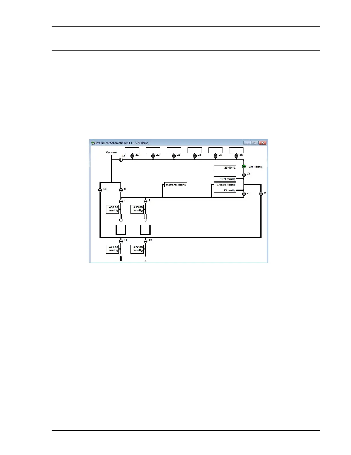
Show Instrument Schematic
Unit [n] - Show Instrument Schematic
Use to display an analyzer schematic. To operate the valves and elevator from this window, Manual
Controls must be enabled (Unit [n] > Enable Manual Control).
Select this option to display a schematic of the ASAP 2460 analysis system. The schematic is a graph-
ical representation of the analysis system including system valves, analysis stations, and dewar
positions. The valves and elevators can be controlled from the schematic when Manual control is
enabled. Refer to Enable Manual Control, page 4-14 for an explanation of the components displayed
on the analysis schematic.
Two-port Instrument Schematic
 Loading...


