Landing/Positioning System
2-73
2
Motion 4000
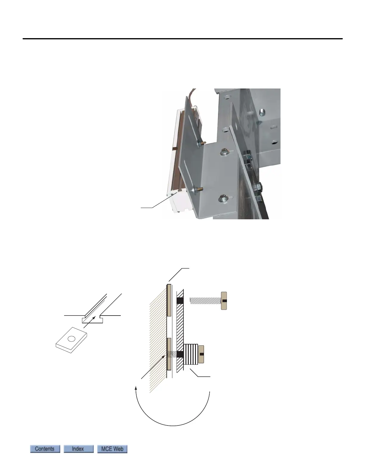
Figure 2.27 Sample Mount B
Alternatively, you can use 8 x 32 channel nuts and screws or 1/4” square head bolts and nuts.
However, if you are inserting the screws toward the body of the sensor, you must be very careful
that you position spacers to prevent the screw from damaging the sensor.
Figure 2.28 Sample Mount C
Slotted mounting holes on bracket
allow adjustment.
The heads of the sensor mounting
bolts are captive in a slot on the
sensor body.
Bolts are 1/4” diameter with
square heads. Use a flat washer
against the mounting bracket, and
a lock washer between the nut and
the flat washer. M6, hex head bolts
may also be used.
Use spacers to adjust the vertical
alignment of the sensor head.
Mounting
channel
8 x 32 Channel nut
Unistrut part #: P7006-0832
Sensor Body
Channel nuts
8 x 32 bolt/screw
Bracket body
Add washers or
shims here
(to) Avoid jamming the bolt end
into the sensor body