Troubleshooting
5-80 Manual # 42-02-2P24
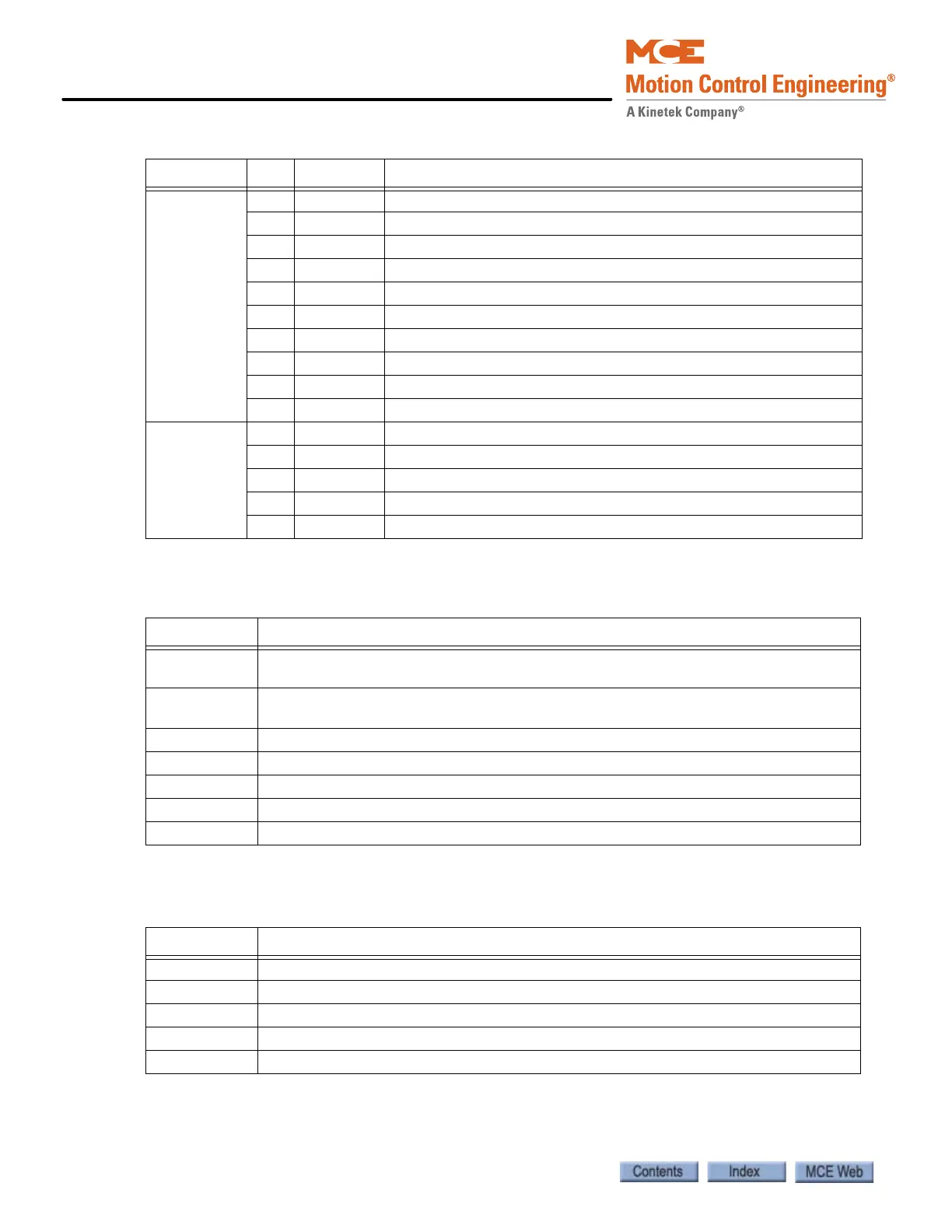
J25 1 EBD1 Emergency Brake, 120VAC
2 EBD2 Emergency Brake, 120VAC
3 EBD3 Emergency Brake, 120VAC
4 EBD4 Emergency Brake, 120VAC
5 EBP12 Emergency Brake, monitoring
6 EBP34 Emergency Brake, monitoring
7 EBPS Emergency Brake, Control
8 RG1 120VAC
9 EBS1 Emergency Brake, Control
10 EBS2 Emergency Brake, Control
J13 1 24VAC 24V input
2 1 Common
3 1 Common
4 2MV 120VAC input
5 2MV 120VAC input
Table 5.28 TC-MPI Board Switches
Switch Function
SW1 4-Position DIP switch. Board configuration. If replacing TC-MPI in the field, set
exactly as original board.
SW2 4-Position DIP switch. Board configuration. If replacing TC-MPI in the field, set
exactly as original board.
RSTMP, S4 Reset button for Motion Processor
RSTB, S1 Reset button for B Processor
RSTA, S2 Reset button for A Processor
EB RST, S3 Emergency Brake reset
EQ RST, S5 Earthquake reset
Table 5.29 TC-MPI Board Diagnostic LEDs
Indicator Function
3.3V Indicates presence of 3.3V power on board
UM Lights if Unintended Motion fault is active
OS Lights if Overspeed fault is active
EQ Lights if Earthquake fault is active
DIA1A-DIA8C Factory diagnostics only
Table 5.27 TC-MPI Board MCE Internal Connections
Connector Pin Label Function