PC Board Quick References
5-79
5
Motion 4000
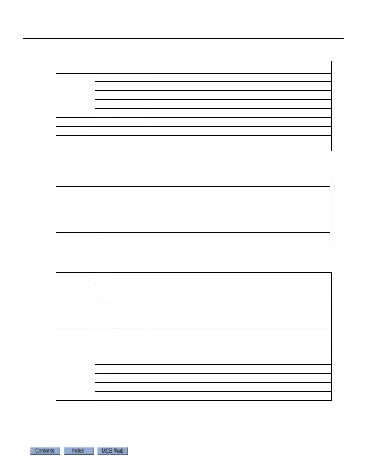
J17
CAN Bus
Hoistway
Position
System
Sensors
1 CANH1 CAN interface to first hoistway position sensor
2 CANL1 CAN interface to first hoistway position sensor
3 CANH2 CAN interface to second hoistway position sensor
4 CANL2 CAN interface to second hoistway position sensor
5 SHLD CAN interface Shield connection
J24 MAGNETEK 9-Pin, D, serial control for Magnetek AC drive
J27 TORQMAX 9-Pin, D, serial control for (Keb) Torqmax drive
J2 INTERNAL
NETWORK
CAN and power connections internal to Controller. Factory connec-
tion. Disconnection will reset board.
Table 5.26 TC-MPI Board Jumpers
Jumper Function
JP1 Normal = A position: Terminating resistor for RS422/485 communication ON.
B position: Removes terminating resistor from circuit.
JP2, JP3, JP4 Terminating resistors for buffered encoder information from drive. When jumpers
are in place, terminating resistors are ON.
JP6 Terminating resistor for internal CAN Bus. When jumper is in place, terminating
resistor is ON.
JP5, JP7 Normal = B position: RG monitoring done on TC-MPI board.
A position: RG monitoring by equipment external to TC-MPI board.
Table 5.27 TC-MPI Board MCE Internal Connections
Connector Pin Label Function
J3 1 PM2 Primary motor contactor
2 2L 120VAC
3BRBP Brake control
4 SPI3 Spare Input (DNT1 if physical directional limits are used, F7 202)
5 SPI4 Spare Input (UNT1 if physical directional limits are used, F7 202)
J9 1 DZRO Door Zone Rear Output
2 DZFO Door Zone Front Output
3 BRC Brake Contactor Complimentary
4 BR Brake Contactor
5 PM Primary motor contactor
6 FBS Full Brake Strength, bypasses brake hold voltage resistor
7 BRP Brake Contactor
8 PMP Primary motor contactor
Table 5.25 TC-MPI Board Customer Connections
Connector Pin Label Function