Troubleshooting
5-78 Manual # 42-02-2P24
Table 5.25 TC-MPI Board Customer Connections
Connector Pin Label Function
J5
CAN Bus
Drive
Control
1 CANH3 CT drive CAN interface CANH
2 CANL3 CT drive CAN interface CANL
3 GND CT drive CAN interface Ground
4 SHLD CT drive CAN interface Shield connection
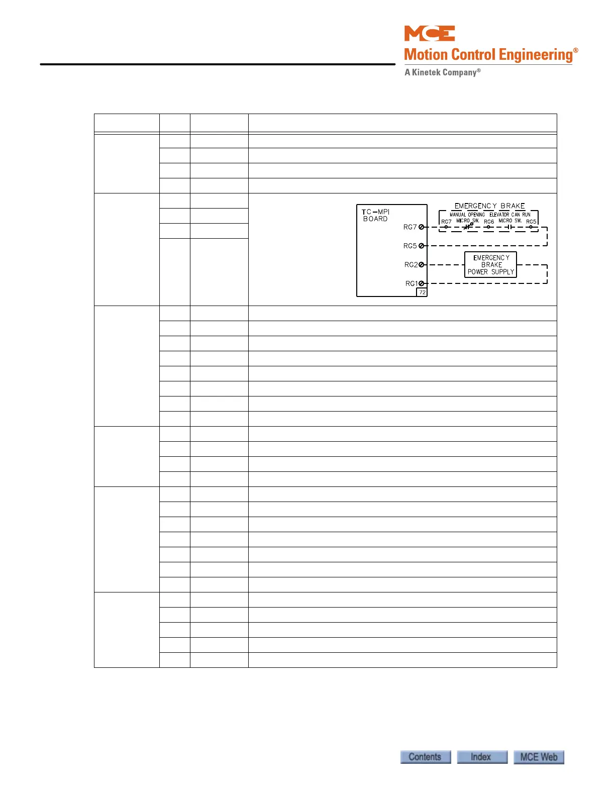
J7
Rope Gripper
240VAC Max
1RG7 Control out
Control in
Analog Ground
120VAC Out
2RG5
3RG2
4RG1
J11
Buffered
encoder sig-
nal from
drive to MPI
board
1 A+ A+ buffered encoder from drive
2 A- A- buffered encoder from drive
3 B+ B+ buffered encoder from drive
4 B- B- buffered encoder from drive
5 Z+ Z+ buffered encoder from drive
6 Z- Z- buffered encoder from drive
7GND Ground
8SHLD Shield
J12
120VAC Max
1 UETS Up Emergency Terminal Switch input (if used)
2 DETS Down Emergency Terminal Switch input (if used)
3 SPI1 Spare Input 1 (assignable per job)
4 SPI2 Spare Input 2 (assignable per job)
J16
Discrete
Drive
Control
1 DPS AC Drive Positive, 16 - 14VDC
2 DNS AC Drive Negative, Ground
3 DRE Torqmax/Keb Drive Enable, Magnetek Drive Common
4 DCOM Torqmax/Keb A2.20 (16-18VDC), Magnetek Enable
5 DRO Drive On input
6 DRDY Drive Ready input
7DFLT Drive Fault input
J20 1 EQ24 24V for counterweight “ring and string” movement detector
2 CW2 Counterweight detector, 24VAC Max
3 CW1 Counterweight detector, 24VAC Max
4 SSI Seismic Sensor Input, 24VAC Max
5 EQIND Earthquake Indicator, 120VAC Max