Appendix
A-6 Manual # 42-02-2P24
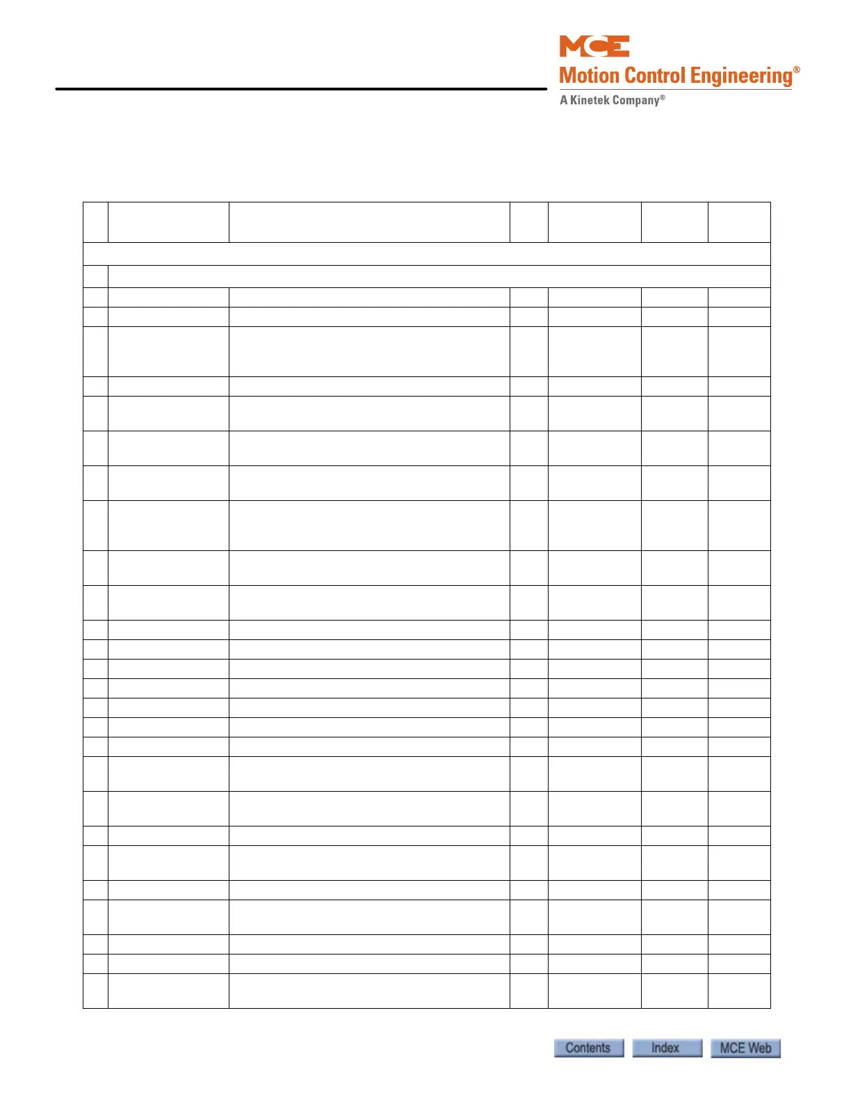
Magnetek Parameters Table
Enter the settings you make while adjusting into the Field column of the following table.
Table A.2 Magnetek AC Drive Table
#
Operator
Display
Parameter Description Unit
Setting
Range
MCE
Defaults
Field Set
Adjust A0
A1 Drive
Contract Car Spd Elevator Contract Speed fpm 0 - 3000 0.1
Contract Mtr Spd Motor Speed at elevator contract speed rpm 50 - 3000 1130
Response Speed regulator sensitivity. If set too high,
motor current and speed will be jittery. If too
small, the motor will be sluggish.
rad/
sec
1.0 - 20.0 10
Inertia System inertia sec 0.25 - 50.00 2.0
Inner Loop Xover Inner speed loop crossover frequency (only
with Ereg speed regulator)
rad/
sec
0.1 - 20.0 2.0
Gain Reduce Mult Speed regulator response percentage to use in
low gain Mode. 100% = no reduction.
% 10 - 100 100
Gain Chng Level Speed level to change to low gain mode
(only with internal gain switch)
% 0 - 100.0 100
Tach Rate Gain Compensates for rope resonance. Use only
after A1, Inertia, and A1, Response, have
been set correctly.
%0 - 30.0 0
Spd Phase Margin Phase margin of speed regulator
(only with PI speed regulator)
o 45 - 90 80
Ramped Stop Time Time to ramp from rated torque to zero (only
with torque ramp down stop function)
sec 0 - 2.50 0.20
Contact Flt Time Time before a contactor fault is declared sec 0.10 - 5.00 0.50
Brake Pick Time Time before a brake pick fault is declared sec 0 - 5.00 0.00
Brake Hold Time Time before a brake hold fault is declared sec 0 - 5.00 0.00
Overspeed Level Threshold for detection of overspeed fault % 100.0 - 150.0 125.0
Overspeed Time Time before an overspeed fault is declared sec 0 - 9.99 1.00
Overspeed Mult Multiplier for overspeed test (U4) % 100 - 150 100
Encoder Pulses Encoder counts per revolution ppr 600 - 10000 1024
Spd Dev Lo Level Range around the speed reference for speed
deviation low logic output
% 00.1 - 10.0 10
Spd Dev Time Time before speed deviation low logic output
is true
sec 0 - 9.99 1.00
Spd DevHi Level Level for declaring speed deviation alarm % 0 - 99.9 20.0
Spd Command Bias Subtracts an effective voltage to actual speed
command voltage
volts 0 - 6.00 0.00
Spd Command Mult Scales analog speed command - 0.90 - 3.00 1.00
Pre Torque Bias Subtracts an effective voltage to actual pre
torque command voltage
volts 0 - 6.00 0.00
Pre Torque Mult Scales pre-torque command - -10.00-10.00 1.00
Zero Speed Level Threshold for zero speed logic output % 0 - 99.99 1.00
Zero Speed Time Time before zero speed logic output is
declared true
sec 0 - 9.99 0.10