Set Up for Construction Operation
2-37
2
Motion 4000
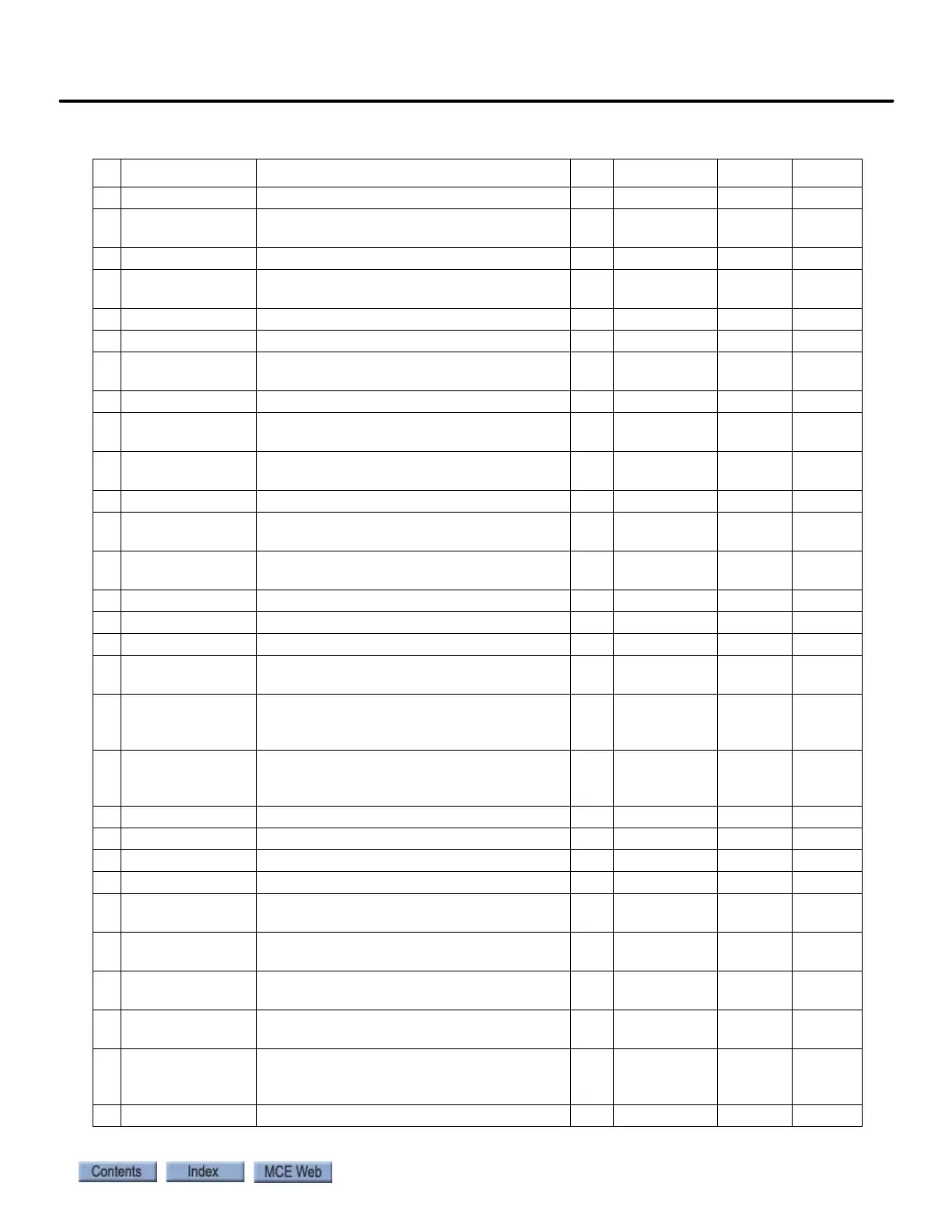
Spd Dev Hi Level Level for declaring speed deviation alarm % 0 - 99.9 10.0 10.0
Spd Command Bias Subtracts an effective voltage to actual speed
command voltage
volts 0 - 6.00 0.00 0.00
Spd Command Mult Scales analog speed command - 0.90 - 5.00 1.00 1.43
Pre Torque Bias Subtracts an effective voltage to actual pre
torque command voltage
volts 0 - 6.00 0.00 0.00
Pre Torque Mult Scales pre-torque command - -10.00-10.00 1.00 1.00
Zero Speed Level Threshold for zero speed logic output % 0 - 99.99 1.00 1.00
Zero Speed Time Time before zero speed logic output is
declared true
sec 0 - 9.99 0.10 0.10
Up/Dwn Threshold Detection threshold, up or down direction % 0 - 9.99 1.00 1.00
Mtr Torque Limit Motoring torque limit. Torque Limit LED will
light when this limit is reached.
% 0 - 275.0 200.0 200.0
Regen Torq Limit Regenerating torque limit. Torque Limit LED
will light when this limit is reached.
% 0 - 275.0 200.0 200.0
Flux Wkn Factor Defines torque limit at higher speeds % 60.0 - 100.0 100.0 100
Ana 1 Out Offset Subtracts an effective voltage to actual analog
output 1
% -99.9 - 99.9 0.00 0.00
Ana 2 Out Offset Subtracts an effective voltage to actual analog
output 2
% -99.9 - 99.9 0.00 0.00
Ana 1 Out Gain Scaling factor for analog output 1 - 0 - 10.0 1.0 1.0
Ana 2 Out Gain Scaling factor for analog output 2 - 0 - 10.0 1.0 1.0
Flt Reset Delay Time Before a fault is automatically reset sec 0 - 120 5 5
Flt Reset / Hour Number of faults allowed to reset automati-
cally per hour
fault 0 - 10 3 3
Up to SPD. Level The logic output function is true when the
motor speed is above the user specified speed
defined here
% 0 - 110.00 080.00 080.00
Mains DIP Speed When enabled by the Main DIP Speed (A1)
parameter, speed is reduced by this percent
when an undervoltage alarm is declared
% 5 - 99.9 25.00 25.00
Run Delay Timer Delays drive recognition of RUN signal. sec 0.00 - 0.99 0.00 0.00
AB Zero Spd Lev Auto Brake Function - N/A to MCE products % 0.00 - 2.00 0.00 0.00
AB Off Delay N/A to MCE products sec 0.00 - 9.99 0.00 0.00
Contactor DO Dly N/A to MCE products sec 0.00 - 5.00 0.00 0.00
TRQ Lim Msg Dly Time duration drive is in torque limit before
Hit Torque Limit message displayed.
sec 0.00 - 10.00 0.50 0.50
SER2 INSP SPD Defines the serial mode 2 Inspection
(only serial mode 2)
ft/
min
0 - 100 30 30
SER2 RS CRP SPD Creep speed used in “rescue mode” ft/
min
0 - 300 10 10
SER2 RS CPR Time Maximum time drive will continue to run at
rescue creep speed (only serial mode 2)
sec 0 - 200 180 180
SER2 FLT TOL Maximum time that may elapse between valid
run time messages before a serial fault is
declared (only serial mode 2)
sec 0.0 - 2.0 0.04 0.04
Rollback Gain Ant-rollback gain - 1 - 20 1 1
Table 2.5 Magnetek AC Drive Table
# Display Parameter Description Unit Range Defaults Factory