Home
Olympus
Security Sensors
EPOCH 6LT
Page 158 (Figure 10-3 Wi-Fi Unsecured Logon Page)
Olympus EPOCH 6LT - Figure 10-3 Wi-Fi Unsecured Logon Page
232 pages
Manual
Save Page as PDF
To Next Page
To Next Page
To Previous Page
To Previous Page
Loading...
DMT
A-10084-0
1EN, Rev
.
2, November 2018
Chapter 10
148
Figure
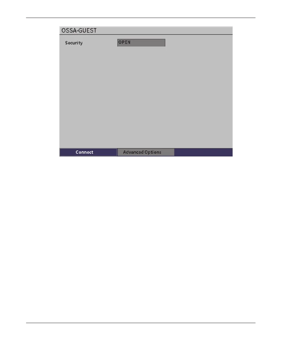
10-3 Wi
-Fi unsecured logon page
A page displays to show the status, s
trength, security
, and IP address of the
connection (see Figure
10-4 on page
149).
157
159
Table of Contents
Main Page
Table of Contents
3
List of Abbreviations
9
Important Information - Please Read before Use
11
Intended Use
11
Instruction Manual
11
Safety Symbols
12
Safety Signal Words
12
Note Signal Words
13
Warranty Information
13
Technical Support
14
Introduction
15
1 Hardware User Interface Overview
17
Figure 1-1 EPOCH 6LT Front Panel
17
Enter Key
18
ESC Key
18
Shift Key
18
Tab Key
18
Adjustment Knob
19
Figure 1-2 Adjustment Knob
19
2 Software User Interface Overview
21
Figure 2-1 Live A-Scan Display Elements
21
Figure 2-2 File Identifier Bar with ID Example
22
Figure 2-3 Measurement Reading Boxes Example
22
File Identifier Bar
22
Gain Adjustment Box
22
Measurement Reading Boxes
22
Figure 2-4 Message Bar with a Message Example
23
Figure 2-5 Message Bar with Flags Displayed
23
Live A-Scan
23
Message Bar
23
Figure 2-6 Example of an A-Scan Waveform with Gates
24
Modes
24
Figure 2-7 Setup Menu (Left) and Sidebar Menu (Right)
25
Figure 2-8 Shortcut Menu
25
3 Setup Mode
27
Setup Menu
27
Figure 3-1 Setup Menu
27
Setup Menu Icons
28
Table 1 Setup Menu Icon Actions
28
Figure 3-2 Dialog Box (Left) and Setup Page (Right)
29
Navigating Dialog Boxes and Setup
29
Figure 3-3 Setup Page as Initially Displayed
30
4 Inspection Mode
33
Figure 4-1 Sidebar Menu
33
Sidebar Menu
34
Sidebar Menu Button Actions
34
Table 2 Button Types
34
Adjustable Value Buttons
35
Figure 4-2 Submenu with Highlighted Adjustable Value
35
Figure 4-3 Enhanced Border Indicates Selected Adjustable Value
35
Using the Sidebar Menu and Submenus
36
Figure 4-4 File Identifier Shortcut Menu
38
File Identifier Shortcut Menu
38
Shortcut Menus
38
Figure 4-5 Highlighted File Identifier Bar
39
Measurement Reading Shortcut Menu
39
Figure 4-6 Measurement Reading Shortcut Menu
40
Figure 4-7 Highlighted Measurement Reading Bar
40
Figure 4-8 Gain Adjustment Shortcut Menu
41
Figure 4-9 Highlighted Gain Adjustment Box
41
Gain Adjustment Shortcut Menu
41
5 Setup
43
Figure 5-1 Create Setup Page and Its Elements
43
Figure 5-2 Settings Menu
44
Opening a Setup Page
44
Using the Virtual Keypad
45
Figure 5-3 Edit Page with Virtual Keypad
46
File Management
47
Instrument Settings
47
User Keys Setup Page
47
Figure 5-4 Default Home Screen (Live A-Scan)
48
Figure 5-5 Custom User Key Setup Page
49
Figure 5-6 G1Start Selected as Home Location
50
Display Setup Page
51
Figure 5-7 Display Setup Page
51
Figure 5-8 X-Axis Grid Mode Options
53
Measurement Setup Page
54
Figure 5-9 Measurement Setup Page
55
Figure 5-10 Example of Measurement Reading Boxes with Icons
56
Table 3 Available Measurement Readings
56
Figure 5-11 Instrument Setup Page
60
Instrument Setup Page
60
Clock Setup Page
62
Figure 5-12 Clock Setup Page
62
Software Options Setup Page
62
Resets Setup Page
63
About Setup Page
64
Figure 5-13 Resets Setup Page
64
Instrument Info Setup
64
Wi-Fi Networks Setup Page
64
Upgrade Setup Page
65
Figure 5-14 Upgrade Setup Page
66
License Setup Page
66
Regulatory Setup Page
66
Diagnostic Test Setup Page
67
Legal Setup Page
67
Figure 5-15 Diagnostic Test Setup Page
68
6 Pulser/Receiver Adjustments
69
Adjusting the Gain (System Sensitivity)
69
Figure 6-1 Highlighted Gain Adjustment Box
69
Setting Reference Gain and Scanning Gain
70
Using the Auto XX% Feature
70
Selecting and Adjusting the Pulser
72
Figure 6-2 Scanning Gain Buttons
72
Energy (Voltage)
73
Figure 6-3 Pulser Dialog Box
73
Damping
74
Pulser Type
74
Pulser Frequency
75
Test Modes
75
Pulse Repetition Frequency (PRF)
76
Adjusting the Receiver
77
Digital Receiver Filters
78
Figure 6-4 Receiver Dialog Box
78
Reject Parameter
79
Waveform Rectification
79
Figure 6-5 Horizontal Line Indicating the Reject Level
80
7 Gates
81
Activating the Gates
81
Measurement Gates 1 and 2
82
Figure 7-1 Gate (G1) Status on
82
Quickly Adjusting Basic Gate Parameters
83
Figure 7-2 Gate 1 and Gate 2 (with Echo-To-Echo Turned On)
83
Figure 7-3 Gate 1 Submenu
84
Gate Measurement Modes
85
Figure 7-4 Gate1 Dialog Box
85
Figure 7-5 Gate Trigger Indicator in Edge (Left) and Peak (Right) Modes
86
Figure 7-6 Gate Trigger Indicator in 1Stpeak (Left) and J-Flank (Right) Modes
87
Viewing Measurement Readings
88
Gate Tracking and Echo-To-Echo Measurements
89
Time-Of-Flight Mode
90
Figure 7-7 Echo-To-Echo Measurement Example
90
Zooming in on a Gate
91
Figure 7-8 Time-Of-Flight Measurement
91
Gate Alarms
92
Threshold Alarms
92
Figure 7-9 Gate Tick Marks Indicating Alarm Threshold Type
93
Minimum Depth Alarm
93
Figure 7-10 Minimum Depth Alarm Marker
94
7.10 Peak Memory
95
Figure 7-11 Peak Memory Signal Envelope Example
95
7.11 Peak Hold
96
7.12 Freeze
97
8 Calibration
99
Basic Setup
99
Figure 8-1 UT Dialog Box
101
Calibration Modes
102
Figure 8-2 Angle Dialog Box
102
Straight Beam Modes
102
Angle Beam Modes
103
Calibration Procedure
103
Figure 8-3 Calibration - Dialog Box Initial Setup
105
Figure 8-4 Calibration - Ready to Auto 80% on Thin Echo
106
Figure 8-5 Calibration - Ready to Collect Thin Echo
107
Figure 8-6 Calibration - Ready to Collect Thick Echo
108
Figure 8-7 Calibration - Successfully Completed
109
9 Data Logger
111
Data File Types
112
Figure 9-1 Settings Menu
112
Incremental File Type
112
2-D Matrix Grid File Type
113
Calibration File Type
113
Data Logger Storage Capacity
113
Saving Data to Active Files
113
Data Logger Setup
114
Create
115
Figure 9-2 Create Setup Page
115
Figure 9-3 File Name Edit
116
File
117
Figure 9-4 File Setup Page
118
Figure 9-5 Name and ID of Open File on the Live A-Scan Display
119
Figure 9-6 Saved File Waveform
120
Figure 9-7 Saved File Data
121
Figure 9-8 Viewing All the Ids in a File
122
Figure 9-9 Saved File Waveform and Data
123
Figure 9-10 Recalled File Data
124
Figure 9-11 Details Setup Page
126
Figure 9-12 Summary Setup Page
127
Manage
127
Figure 9-13 Manage Setup Page
128
Figure 9-14 Edit Setup Page
129
Figure 9-15 Copy Setup Page
130
Figure 9-16 Delete Dialog Box
131
Figure 9-17 Clear Dialog Box
131
Figure 9-18 Select ID Setup Page
132
Memo
132
Figure 9-19 Memo Setup Page
133
Figure 9-20 Memo Dictionary Page
134
Figure 9-21 Memo Dictionary Page - Editing a Label
135
Figure 9-22 Memo Dictionary Page - Inserting Label Info
136
Backup|Restore
137
Figure 9-23 Memo Dictionary Page - Inserted Info
137
Figure 9-24 Backup|Restore Setup Page
138
Grid View
140
Activating the Grid View
140
Configuring the Grid
141
Figure 9-25 Grid Dialog Box
141
Using the Grid
142
Figure 9-26 Grid View on the Live A-Scan Display
143
Video Recorder
145
Activating the Video Recorder
145
Figure 9-27 Grid Controls in a Saved File
145
Figure 9-28 Video Sidebar Submenu
146
Recording and Saving Video
146
Figure 9-29 Recording in Progress
147
Figure 9-30 Create Video File Setup Page
148
Figure 9-31 Video Files Setup Page
149
Working with Video Files
149
Figure 9-32 Video Review Setup Page
150
Figure 9-33 Import (Video File) Setup Page
152
10 Wi-Fi Networks
155
10.1 Connecting to a Wireless LAN (Wi-Fi) Network
155
Figure 10-1 Wi-Fi Networks Setup Page
156
Figure 10-2 Wi-Fi Secure Logon Page
157
Figure 10-3 Wi-Fi Unsecured Logon Page
158
10.2 Adding a Wireless LAN (Wi-Fi) Network
159
Figure 10-4 Wi-Fi Connection Status Page
159
Figure 10-5 Add Network Setup Page
160
11 Software Features and Options
161
11.1 Defining Licensed and Unlicensed Software Features
161
11.2 Activating Software Options
162
Figure 11-1 Software Options Setup Page
162
11.3 Dynamic DAC/TCG
163
Enabling the DAC/TCG Feature
164
Applying Reference Correction
165
Building a DAC Curve in Standard or ASME III Mode
166
Figure 11-2 DAC/TCG Dialog Box
166
Figure 11-3 DAC/TCG Sidebar Submenu
167
Figure 11-4 First DAC Point
168
Figure 11-5 Second DAC Point
169
Figure 11-6 Completed DAC Curve
170
Figure 11-7 Partial DAC Curve with each Echo Set to 80 % FSH
171
DAC Inspection Mode
172
Figure 11-8 Completed DAC Curve
172
Figure 11-9 Completed DAC Curves in TCG View Mode
173
Figure 11-10 a Small Range DAC
174
Gain Adjustment Options
174
Figure 11-11 Standard DAC with 6 Db Scanning Gain
175
Figure 11-12 Standard DAC with Scanning Gain off
176
Figure 11-13 DAC with 6 Db Scan Gain - Reference Correction Active
177
Figure 11-14 DAC Curves with Adjusted Gain
178
Figure 11-15 JIS Mode
179
Jis Dac
179
Custom DAC Curves
180
Figure 11-16 JIS Curves
180
Figure 11-17 Custom DAC Setup
181
11.4 Dgs/Avg
182
Figure 11-18 Completed Custom DAC
182
Enabling the DGS/AVG Option
183
Figure 11-19 DGS/AVG Dialog Box
184
Figure 11-20 Reference Reflector before Capture
186
Curve-Adjustment Options
187
Figure 11-21 DGS/AVG Curves on the Screen
187
Transfer Correction
187
DGS/AVG Curve Gain
188
Figure 11-22 (Ref) Gain Adjustment Box
188
Figure 11-23 Gain Curve Adjusted DGS
189
Registration Level Adjustment
189
Relative Attenuation Measurement
190
11.5 AWS D1.1/D1.5 Weld Rating Software
191
Enabling the AWS D1.1 Option
192
Figure 11-24 AWS Dialog Box
192
Figure 11-25 Active AWS with a Ref Level of 50
193
Figure 11-26 AWS Ref B Value Dialog Box
194
Figure 11-27 Active AWS with D Rating
195
Scanning Gain
195
Calculating a and C Values
196
11.6 Back Wall Echo Attenuator
196
Enabling the BEA Option
197
Figure 11-28 Activating the BEA
198
Operating the BEA
198
11.7 Corrosion Module
199
Figure 11-29 Adjusting Back Wall Gain
199
Key Features
200
Corrosion Module Modes
201
Figure 11-30 Corrosion Module Grid View
201
Figure 11-31 Scanning Mode Screen
202
Figure 11-32 Precision Mode Screen
203
Corrosion Module Activation and Setup
204
Figure 11-33 Probe Detected Dialog Box
204
Figure 11-34 Corrosion Dialog Box
205
Figure 11-35 Transducer Setup Page
206
Figure 11-36 Do-Zero Dialog Box
206
Figure 11-37 Incorrectly Triggered Measurement
208
Figure 11-38 AGC off in Precision Mode
209
Figure 11-39 Adjust Gain Value in Precision Mode
210
Figure 11-40 Correctly Triggered Measurement
211
Figure 11-41 Corrosion Dialog Box
212
Figure 11-42 Receiver Dialog Box
213
Figure 11-43 Echo-To-Echo Measurement
214
Figure 11-44 Shear Wave Measurement Error
215
Figure 11-45 Corrosion Sidebar Menu (G2Start)
216
Table 4 Flag Descriptions
217
List of Figures
221
List of Tables
225
Index
227
Other manuals for Olympus EPOCH 6LT
User Manual
66 pages
Getting Started Guide
8 pages
Related product manuals
Olympus EPOCH 600
64 pages
Olympus EPOCH 1000 Series
364 pages
Olympus Panametrics Epoch 4 Plus
188 pages
Olympus nortec 600
374 pages
Olympus Sonic 1200S/HR
154 pages
Olympus OmniScan X3
8 pages