EasyManua.ls Logo

Panasonic AFP7MC16EC

Panasonic AFP7MC16EC
504 pages
To Next Page IconTo Next Page
To Previous Page IconTo Previous Page
Loading...
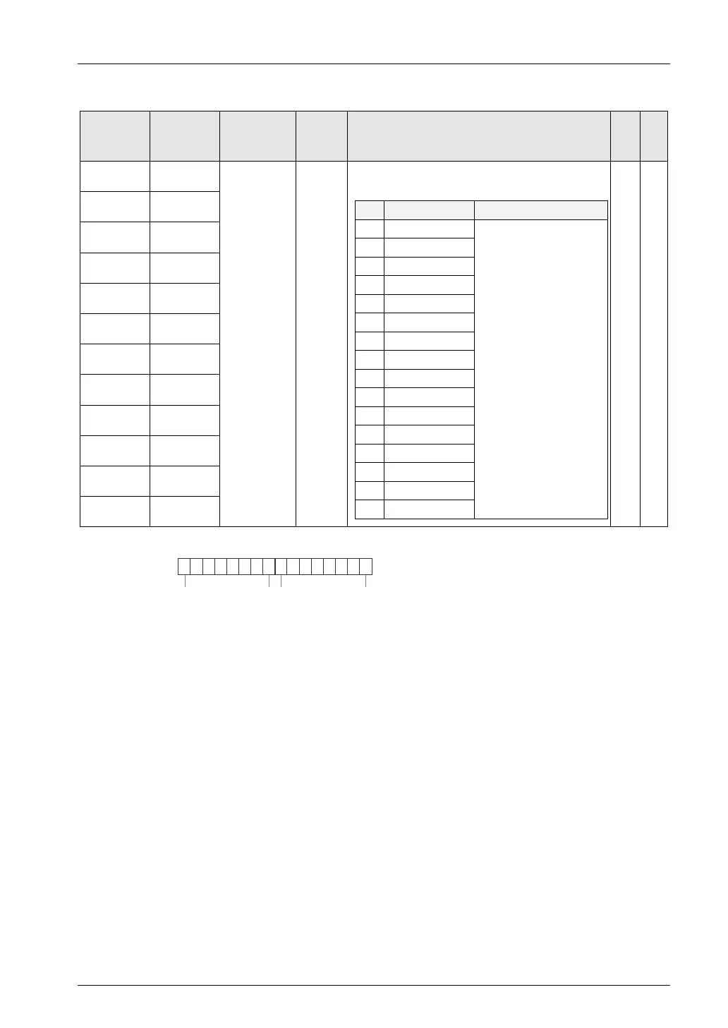
16.4 Unit Memories (Input and Output Control Areas)
16-25
: Available, -: Not available
Slave no.
Unit
memory
no. (Hex)
Name Default
Description R W
1-16 UM 0016B
Error
Indicator
annunciation
H0
Indicates the state of error indicator (ESC register
#130_bit4) of each slave device.
bit
Name
Description
0 Node 1+16n
0OFF
1ON
1 Node 2+16n
2 Node 3+16n
3
Node 4+16n
4 Node 5+16n
5 Node 6+16n
6 Node 7+16n
7
Node 8+16n
8 Node 9+16n
9 Node 10+16n
10 Node 11+16n
11
Node 12+16n
12 Node 13+16n
13 Node 14+16n
14 Node 15+16n
15
Node 16+16n
-
17-32 UM 0016C
33-48 UM 0016D
49-64 UM 0016E
65-80 UM 0016F
81-96 UM 00170
97-112 UM 00171
113-128 UM 00172
129-144 UM 00173
145-160 UM 00174
161-176 UM 00175
177-192 UM 00176
(Note 1): Sixteen node numbers are allocated to each area (1 word).
bit no.
15 08 7
9 1816
Node no.
25 172432
41 334048
57 495664
73 657280
89 818896
105 97104112
121 113120128
137 129136144
153 145152160
169 161168176
185 177184192

Table of Contents

Related product manuals