Setting up Compax3
C3I10T10
192-120100 N16 C3I10T10 - December 2010
Controller structures
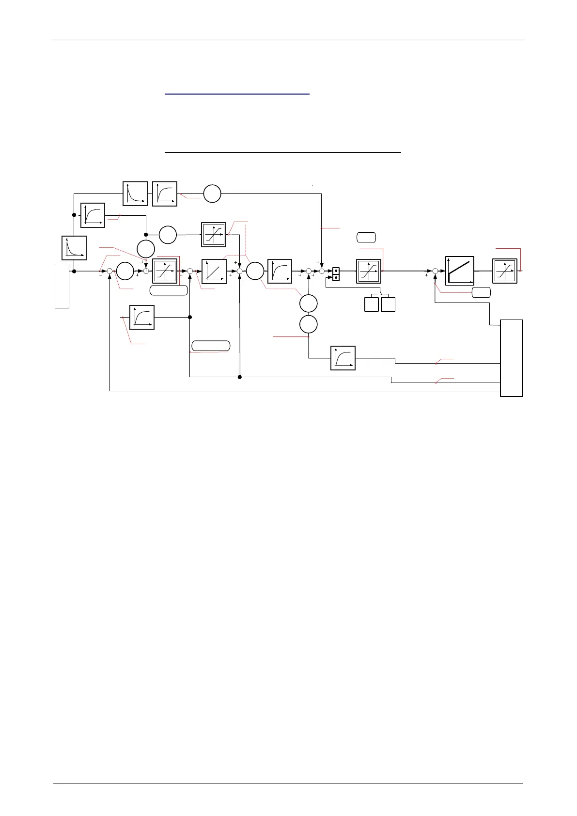
Controller structure step/direction or encoder input
In this chapter you can read about:
........................................................ 132
±10V analog speed setpoint .......................................................................................... 133
±10V analog current setpoint ......................................................................................... 134
T
K
p
,T
N
T
1
i
mR
*
Synchronous
Motor
Asynchronous
Motor
K
I
682.7
2010.2
688.19
682.6
688.14
681.6
680.6
681.9
681.10
680.4
681.11
681.4
682.4
688.18
688.11
2010.4
2100.2
2100.20
2100.3
2100.4
2100.8
2100.9
2010.1
2100.20
2220.4
2220.1
2210.1
2210.2
T
2100.21
682.5
681.5
Istwerterfassung
Actual Value Monitoring
2100.7
T
T
2011.5
2011.4
T
T
Demand acceleration
External Signale
Monitoring
Demand Velocity
Demand position
Velocity
feedforward
Demand
velocity
Following error
actual velocity
filtered
Control deviation
of velocity
Acceleration feedforward
Feedforwaed
current & jerk
demand
current r.m.s.
Voltage control
signal
Actual acceleration
filtered
Demand
velocity
actual
velocity
Velocity controller
Stiffness
Damping
Inertia
Current Controller
Bandwidth
Attenuation
Actual current r.m.s.
(torque producing)
Actual velocity
unfiltered
Actual acceleration
unfiltered
Controller structure step/direction or encoder input
 Loading...


