Parameter Descriptions 2-151
7000-TD002A-EN-P – September 2007
Standard XIO Fault Input [StndXIO FltInput]
Linear Number: 431
Access Level: Advanced
Read/Write: Read Only
This parameter specifies the state of the fault inputs on the standard XIO card. It should be noted that the
faults have a fixed assignment and cannot be changed. If there is a fault, the corresponding bit in this
parameter will go from one to zero, indicating a loss of the 120V signal to the XIO card. This parameter is
further processed by the drive control according to the corresponding class parameter in Alarm Config
group. The final result is updated in either parameter Stnd XIO Fault or Stnd XIO Warning depending on
the fault configuration. If a particular input is not used, it should be masked or tied high. There are a total
of 6 fixed fault inputs. The text accompanying the fault cannot be changed. The ConvFan Fbk is not
processed as an XIO Fault and is treated differently by the drive control software.
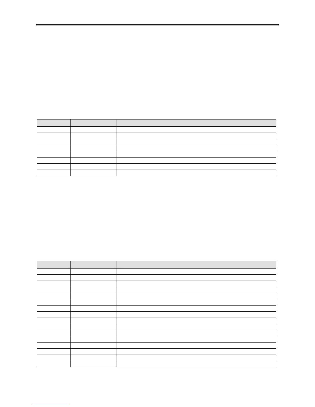
Bit Enum Text Description
0 Input Protn1 Input Protection 1 fault
1 TxReacOvrTmp Isolation Transformer/Line Reactor Over temperature fault
2 DCLinkOvrTmp DC Link / Common-Mode Choke Over temperature fault
3 Motor Protn Motor Protection fault
4 Input Protn2 Input Protection 2 fault
5 AuxTrp/TxFan Auxiliary Trip/ Isolation Transformer Fan Fault
6 ConvFan Fbk Main Cooling Fan Status Feedback
7 Unused
External Fault XIO [Ext Fault XIO]
Linear Number: 232
Access Level: Advanced
Read/Write: Read Only
This parameter specifies the state of the external fault inputs on the optional XIO card. There are 16
external fault inputs available, from External 1 to External 16. If there is a fault, the corresponding bit in
this parameter will go to zero, indicating a loss of the 120V signal to the XIO card. This parameter is
further processed by the drive control according to the corresponding class parameter in Alarm Config
group. The final result is updated in either parameter External Fault or External Warning depending of the
fault configuration. If an external fault input is not used it should be masked or tied high. The text
accompanying the fault can be changed and adapted to the customer’s requirement.
Bit Enum Text Description
0 External1 External Fault Input 1
1 External2 External Fault Input 2
2 External3 External Fault Input 3
3 External4 External Fault Input 4
4 External5 External Fault Input 5
5 External6 External Fault Input 6
6 External7 External Fault Input 7
7 External8 External Fault Input 8
8 External9 External Fault Input 9
9 External10 External Fault Input 10
10 External11 External Fault Input 11
11 External12 External Fault Input 12
12 External13 External Fault Input 13
13 External14 External Fault Input 14
14 External15 External Fault Input 15
15 External16 External Fault Input 16

 Loading...


