1-38 Functional Description
7000-TD002A-EN-P – September 2007
Power Factor Compensation This feature is available in drives with PWM rectifier to compensate
leading power factor at low motor speeds with a fan/pump type load.
Leading or lagging power factor at high motor speeds (or even above
base speed) can also be compensated or improved. The control of
power factor is realized by either controlling the modulation index of
the inverter using Space Vector Modulation (SVM) gating technique
or by adjusting the motor flux profile.
Contact factory for the availability of this feature.
Analog Outputs A total of seventeen programmable analog outputs are provided on
various boards. They are classified as customer use or diagnostic use.
See tables below. There are eight analog outputs on DPM which are
intended for diagnostic purposes and are available as test points for
connection to an oscilloscope or chart recorder. These analog outputs
are 8-bit, non-isolated, with a range of -10V to +10V. The ACB also
has one isolated 4-20mA analog output and 8 non-isolated analog
outputs for connection to external devices such as meters or isolation
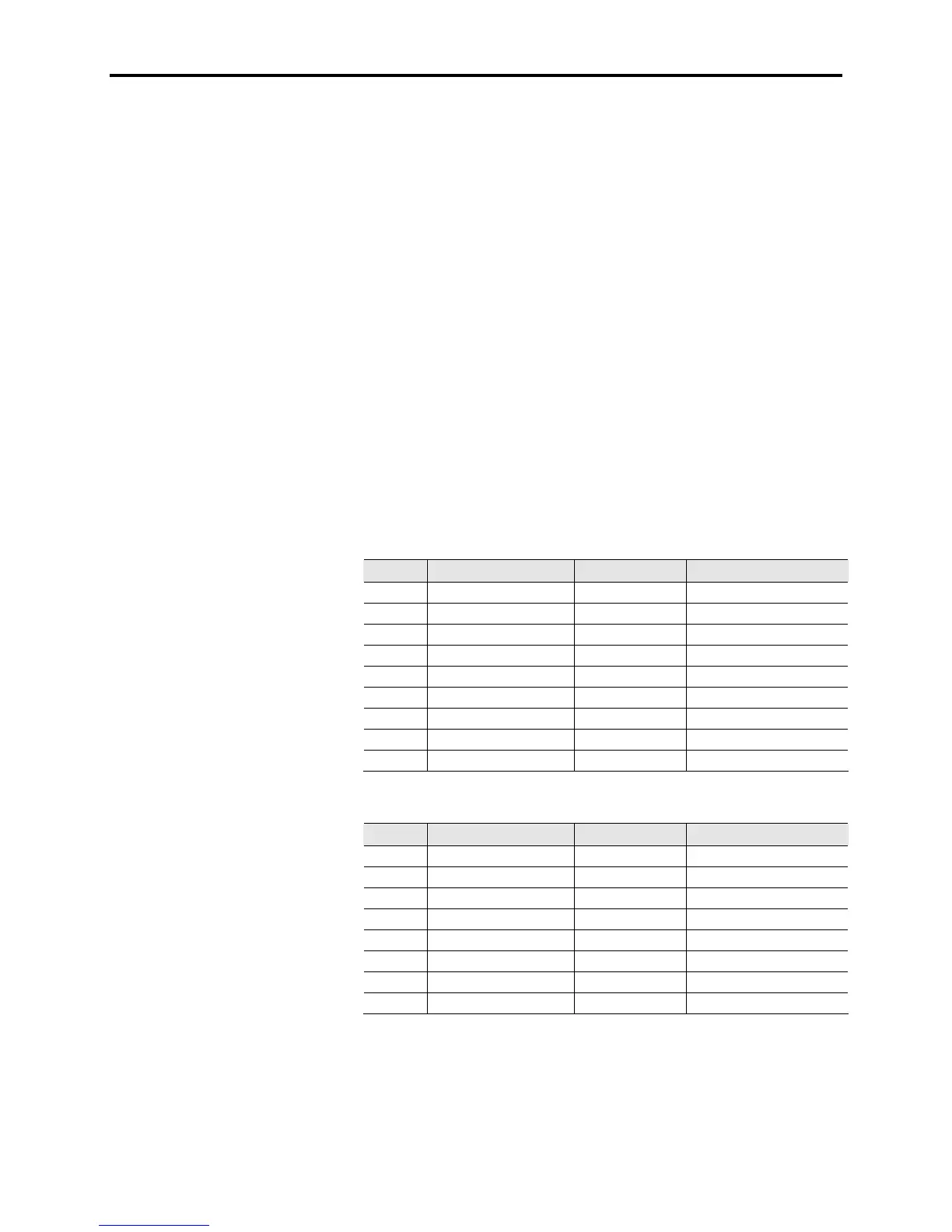
modules. The allocation of the analog outputs is shown below:
Table 1.D – Analog Outputs Customer Use
No. Output Board Description
1 Meter1 ACB Connector J10
2 Meter2 ACB Connector J10
3 Meter3 ACB Connector J10
4 Meter4 ACB Connector J10
5 Output1 ACB Connector J8
6 Output2 ACB Connector J8
7 Output3 ACB Connector J8
8 Output4 ACB Connector J8
9 4-20mAOut ACB Connector J8
Table 1.E – Analog Outputs Diagnostic Use
Output Board Description
1 RecTstPt1 DPM RTP1
2 RecTstPt2 DPM RTP2
3 RecTstPt3 DPM RTP3
4 RecTstPt4 DPM RTP4
5 InvTstPt1 DPM ITP1
6 InvTstPt2 DPM ITP2
7 InvTstPt3 DPM ITP3
8 InvTstPt4 DPM ITP4
Any parameter or variable can be assigned to any analog output.
Only the outputs for customer use can be scaled by using the
corresponding scaling factor.

 Loading...


