Parameter Descriptions 2-17
7000-TD002A-EN-P – September 2007
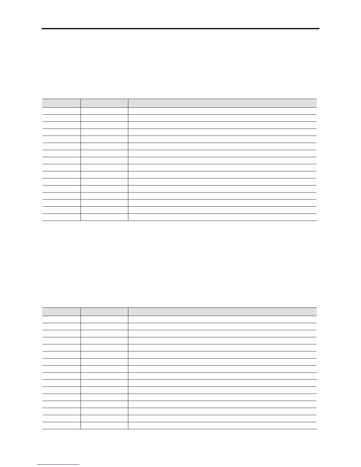
Inverter Control Flags 3 [InvControl Flag3]
Linear Number: 446
Access Level: Service
Read/Write: Read Only
This word indicates various status bits within the inverter control. The word can be used in trending to
assist in determining what the rectifier control is doing in a normal or abnormal situation. A 1 in a location
indicates that condition is active, and a 0 indicates the condition is inactive.
Bit Enum Text Description
0 PF Achieved Desired power factor compensation has been achieved
1 RestartExprd AutoRestart Delay timer has expired
2 PFC Leading Leading Power factor compensation has been enabled
3 Out Dschrgd Motor filter capacitors have been discharged to 5% of rated
4 UWV Seq UWV Sequence enabled
5 IsoTx Fan1 Isolation Transformer 1 Fan is ON
6 IsoTx Fan2 Isolation Transformer 2 Fan is ON
7 ESP Drive ESP Drive selected
8 Restart Mode Auto Restart mode enabled
9 Cool Fans On Drive Cooling Fans ON
10 PFC Optimal Optimal Power factor compensation has been enabled
11 PFC Mod Ctrl Power factor compensation using modulation index control
12 Flying Strt1 Flying Start State 1
13 Flying Strt2 Flyig Start State 2
14 Flying Start Flying Start mode is active
15 PFC FlxRange Flux limit has been reached while compensating for line power factor
Inverter Analog Self Test Code 1 [InvAnlg SelfTst1]
Linear Number: 96
Access Level: Service
Read/Write: Read Only
This parameter specifies the power-up diagnostic results on the Analog Control Board. It refers to the
signals used by the inverter (Slave) processor. If the software detects a problem with the analog signals
into the board, or the board itself, an InvAnlg SelfTest fault will appear. This parameter will help indicate
which signals are causing the problem. The action should be to investigate all the connections and
feedback paths related to that signal before changing the ACB or the DPM. This is a self-test fault that
will only occur at initial power-up.
Bit Enum Text Description
0 HECSU Offset Phase U Motor Current Offset High
1 HECSW Offset Phase V Motor Current Offset High
2 UV Offset Phase UV Motor Voltage Offset High
3 VW Offset Phase VW Motor Voltage Offset High
4 VSAB Offset Bypass UV Voltage Offset High
5 VSBC Offset Bypass VW Voltage Offset High
6 2UV Offset Master Bridge Phase UV Voltage Offset High (for Synch. Transfer)
7 2VW Offset Master Bridge Phase VW Voltage Offset High (for Synch. Transfer)
8 VMDC1 Offset Motor Side DC Link Voltage Offset High
9 VMDC2 Offset Motor Side DC Link Voltage Offset High
10 UV_2 Offset Phase UV Motor Voltage Offset High (used for low motor voltage)
11 VW_2 Offset Phase VW Motor Voltage Offset High (used for low motor voltage)
12 MFCN Offset Motor Filter Capacitor Neutral Voltage Offset High
13 VZS Offset Motor Zero Sequence Voltage Offset High
14 UV_NF Offset Unfiltered Phase UV Motor Voltage Offset High
15 VW_NF Offset Unfiltered Phase VW Motor Voltage Offset High
Contact factory for availability

 Loading...


