2-16 Parameter Descriptions
7000-TD002A-EN-P – September 2007
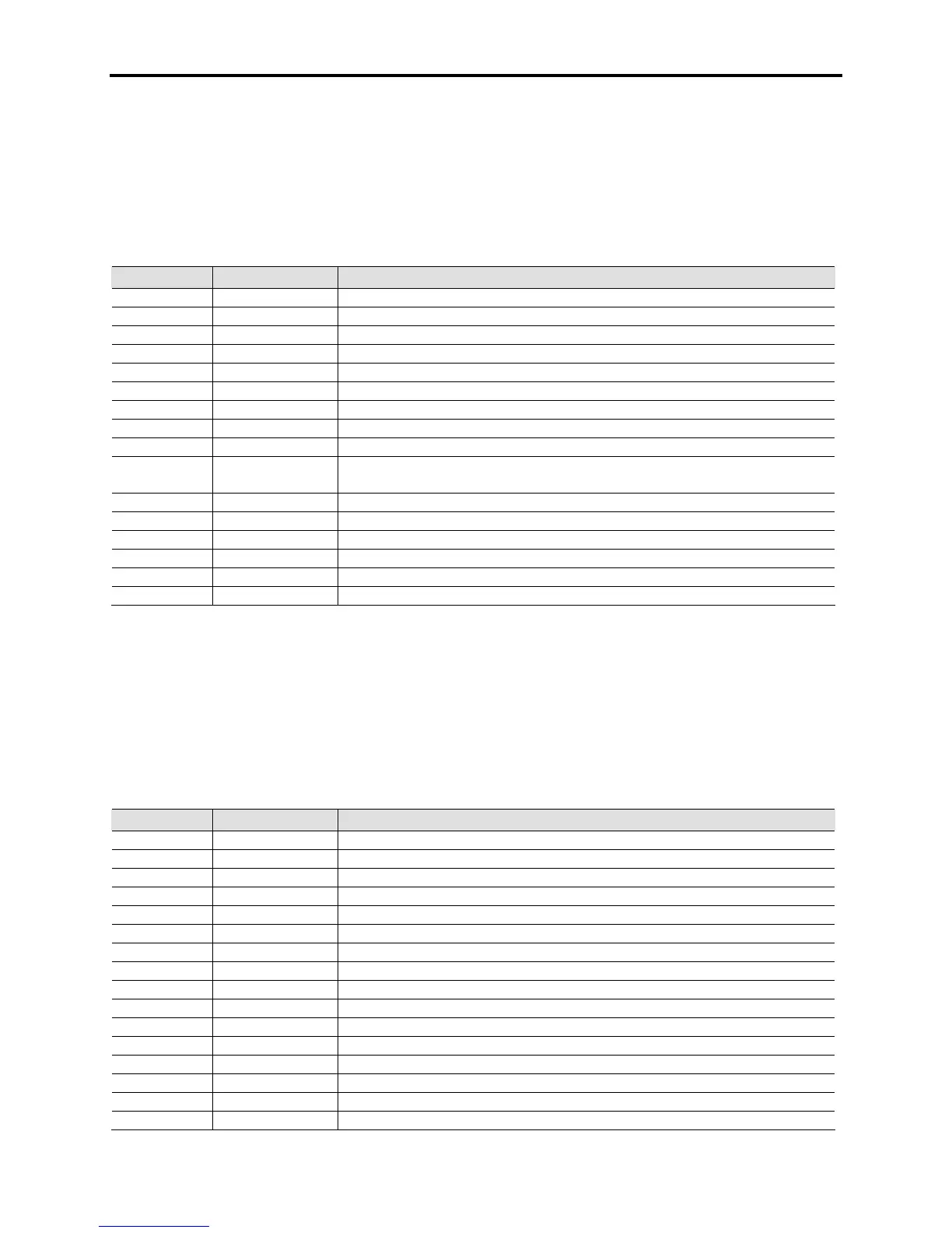
Inverter Control Flags 1 [InvControl Flag1]
Linear Number: 265
Access Level: Service
Read/Write: Read Only
This word indicates various status bits within the inverter control. The word can be used in trending to
assist in determining what the rectifier control is doing in a normal or abnormal situation. A 1 in a location
indicates that condition is active, and a 0 indicates the condition is inactive.
Bit Enum Text Description
0 Mtr PLL Lock Inverter control is locked to the rotor flux position
1 SpdRamp Enbl Torque Ramp is complete and the speed ramp has been enabled
2 Mtr Rvs Seqn The output voltage is not UVW
3 Close Loop The drive is operating in closed-loop mode
4 FlxFbk Enbl The drive is using the measured flux feedback from the motor
5 FreqFbk Enbl The drive is using the measured stator frequency from the motor
6 Gate Freeze The inverter is in Gate Freeze mode
7 Scurve Prof The drive is running with an S-Curve Speed Profile
8 Drv Crit Flt Inverter has detected a Critical Fault
9 TrqRamp Enbl Motor Flux Time has expired and the drive is increasing the torque
reference to TrqCmd0 Snsrless or TrqCmd0 Tach
10 Coast Stop Not Currently Active
11 PID Enabled PID process control is enabled
12 TachFbk Optn The drive has a Tachometer/Encoder feedback signal available
13 TachFbk Enbl The drive is running with Tachometer/Encoder Feedback enabled
14 Torque Lmt The drive is in Torque Limit
15 InvFlg1Bit15 Unused bit
Contact factory for availability
Inverter Control Flags 2 [InvControl Flag2]
Linear Number: 642
Access Level: Service
Read/Write: Read Only
This word indicates various status bits within the inverter control. The word can be used in trending to
assist in determining what the rectifier control is doing in a normal or abnormal situation. A 1 in a location
indicates that condition is active, and a 0 indicates the condition is inactive.
Bit Enum Text Description
0 InternlStart Internal Start Command from Setup Wizard
1 InternalStop Internal Stop Command from Setup Wizard
2 AutotuneCncl Autotune has been aborted
3 Discharging The Line filters capacitors are discharging (more than 50V)
4 Dvc Short The Inverter has detected a shorted SGCT
5 CtrlPwr Loss The drive is in a Control Power Loss mode
6 AC Fail The drive has detected an AC power loss condition
7 InvAnlgTstDn Inverter Analog test is done
8 FreeWhlReset Handshake for Freewheel Mode
9 InvSGCT Pwr Inverter SGCTs have Power
10 AC Pwr Fail The drive has detected an AC power loss condition from the ACB
11 InvDiag Done The inverter diagnostics have been completed
12 InvTemp Loss The inverter temperature feedback is missing
13 VdcVnVSBInst DC and neutral voltage feedback board is installed
14 Mtr OL Pend Motor Overload is Timing
15 SpeedRampRvs Ramp reversing enabled

 Loading...


