2-18 Parameter Descriptions
7000-TD002A-EN-P – September 2007
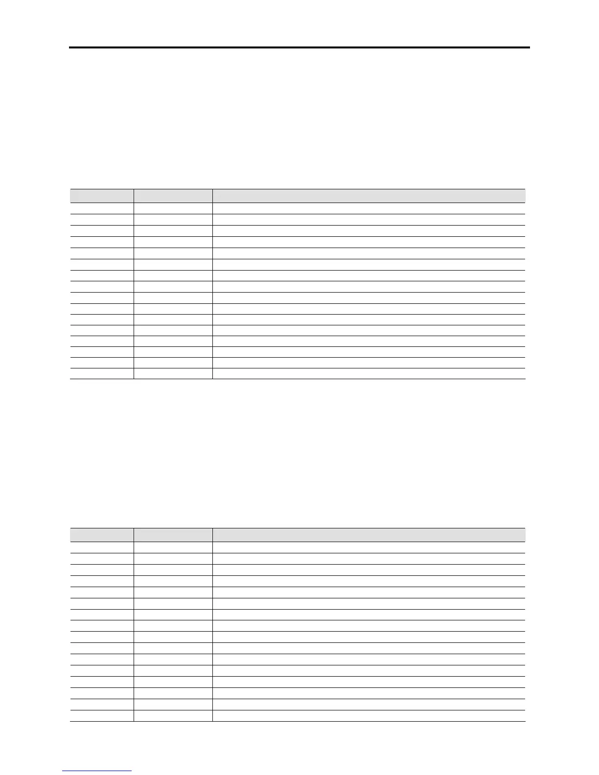
Inverter Analog Self Test Code 2 [InvAnlg SelfTst2]
Linear Number: 251
Access Level: Service
Read/Write: Read Only
This parameter specifies the power-up diagnostic results on the Analog Control Board. It refers to the
signals used by the inverter processor. If the software detects a problem with the analog signals into the
board, or the board itself, an InvAnlg SelfTest fault will appear. This parameter will help indicate which
signals are causing the problem. The action should be to investigate all the connections and feedback
paths related to that signal before changing the ACB or the DPM. This is a self-test fault that will only
occur at initial power-up. Ignoring the faults can results in abnormal drive behavior.
Bit Enum Text Description
0 AC1 Offset Offset measured on AC control power #1
1 AC2 Offset Offset measured on AC control power #2
2 AC3 Offset Offset measured on AC control power #3
3 AC4 Offset Offset measured on AC control power #1
4 AP0 Offset Offset on Converter air flow Air Pressure 0 Sensor
5 AP1 Offset Offset on Isolation transformer pressure circuit.
6 AOUT_DAC Reserved for future use
7 METER_DAC Reserved for future use
8 TRIP_DAC Reserved for future use
9 Unused
10 Unused
11 Unused
12 Unused
13 Unused
14 Unused
15 Unused
Contact factory for availability
Rectifier Analog Self Test Code 1 [RecAnlg SelfTst1]
Linear Number: 473
Access Level: Service
Read/Write: Read Only
This parameter specifies the power-up diagnostic results on the Analog Control Board. It refers to the
signals used by the rectifier (Master) processor. If the software detects a problem with the analog signals
into the board, or the board itself, a RecAnlg SelfTest fault will appear. This parameter will help indicate
which signals are causing the problem. The action should be to investigate all the connections and
feedback paths related to that signal before changing the ACB or the DPM. This is a self-test fault that
will only occur at initial power-up.
Bit Enum Text Description
0 CT2U Offset Master Bridge Phase 2U Current Offset High
1 CT2W Offset Master Bridge Phase 2V Current Offset High
2 CT3U Offset Slave 1 Bridge Phase 3U Current Offset High
3 CT3W Offset Slave 1 Bridge Phase 3V Current Offset High
4 CT4U Offset Slave 2 Bridge Phase 4U Current Offset High
5 CT4W Offset Slave 2 Bridge Phase 4V Current Offset High
6 2UV Offset Master Bridge Phase UV Voltage Offset High
7 2VW Offset Master Bridge Phase VW Voltage Offset High
8 3UV Offset Slave 1 Bridge Phase UV Voltage Offset High
9 3UW Offset Slave 1 Bridge Phase VW Voltage Offset High
10 4UV Offset Slave 2 Bridge Phase UV Voltage Offset High
11 4UW Offset Slave 2 Bridge Phase VW Voltage Offset High
12 2UV_NFOffset Unfiltered Master Bridge Phase UV Voltage Offset High
13 2VW_NFOffset Unfiltered Master Bridge Phase VW Voltage Offset High
14 3UV_NFOffset Unfiltered Slave 1 Bridge Phase UV Voltage Offset High
15 3VW_NFOffset Unfiltered Slave 1 Bridge Phase VW Voltage Offset High

 Loading...


