Assembly
ENVI-MAG Manual A2-7
Preparation
Upper sensor
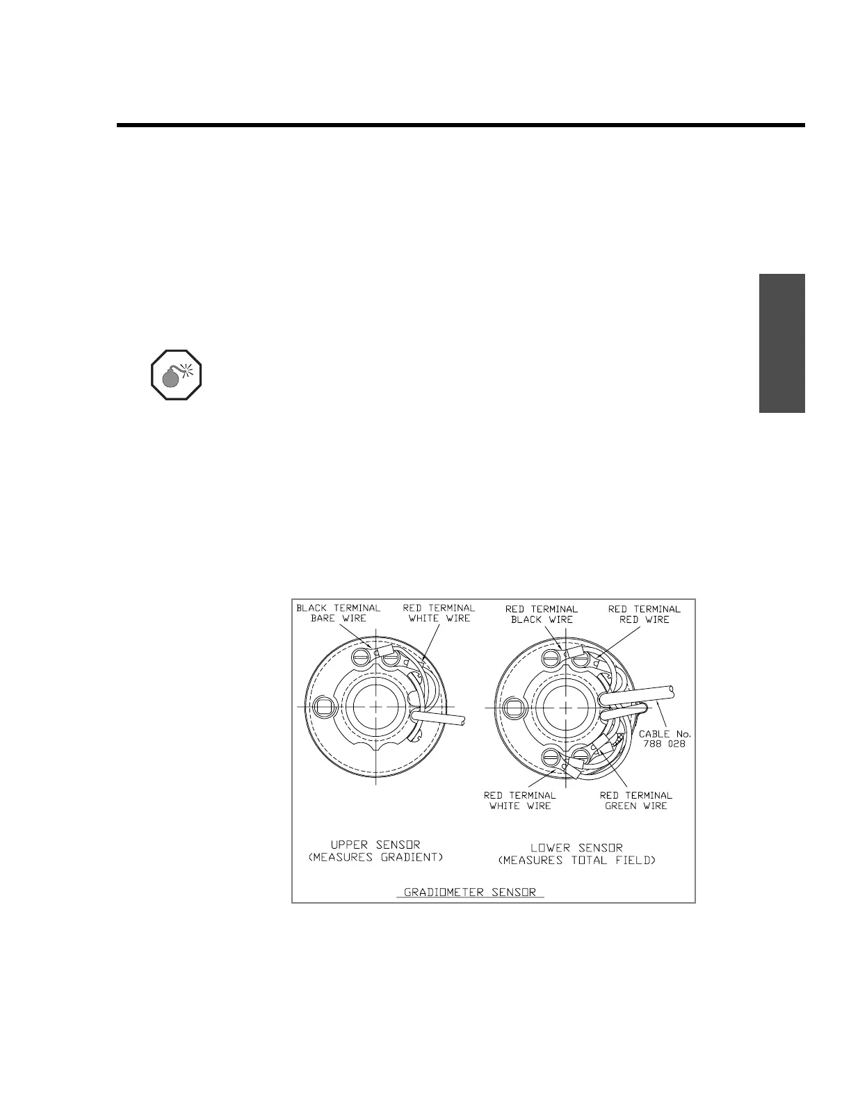
12. Select the upper sensor–it only has a pair terminals at the 12 o’clock
position. (See “Figure A-5Gradiometer sensor cabling” on page A2-7.)
13. Attach the upper sensor to the lower one by placing the shaft of the
lower sensor into the socket of the upper one while rotating slightly
counter-clockwise. When they are fully engaged, firmly twist them
clockwise against each other.
Warning: Both sensors must have their directional marks aligned in the same
manner, i.e. the N on the top sensor must be in-line with the N on the
bottom sensor.
14. Remove the cable hold-down plate of the upper sensor by unscrewing
the screws at the 2 o’clock and 4 o’clock positions.
15. Connect the white wire of the two-conductor cable coming from the
lower sensor to the terminal at the 1 o’clock position.
16. Connect the bare wire of the two-conductor cable coming from the
lower sensor to the terminal at the 11 o’clock position.
17. Re-attach the cable hold-down plate.
Figure A-5 Gradiometer sensor cabling
 Loading...