145
LOGO! Manual
A5E00380835-01
Up/down counter (actual value Cnt,
see Chapter 4.4.13).
Select the required function by means of the block number.
The timebase is configurable. For information on valid
ranges and parameter defaults, refer to Chapter 4.4.1.
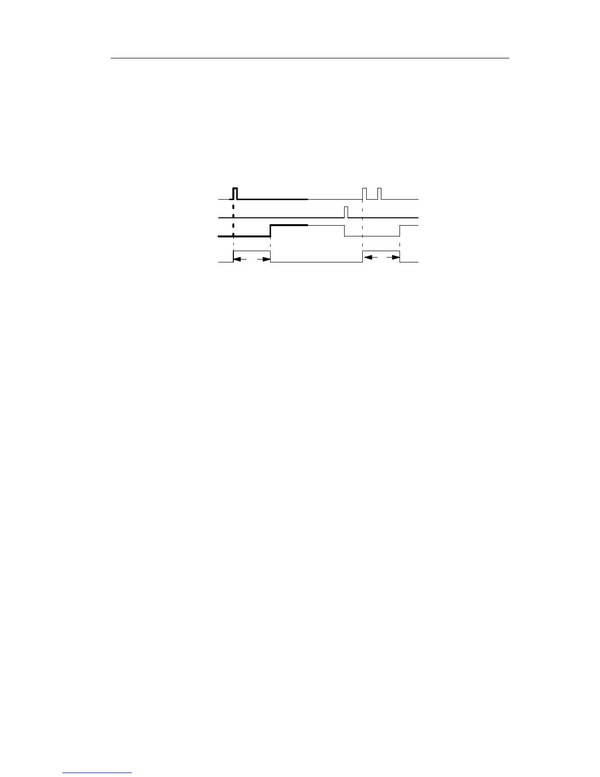
Timing diagram
Trg
T
T
a
expires
Q
R
T
The bold section of the timing diagram is also shown in the symbol of
the retentive on-delay.
Functional description
The 0 to 1 signal transition at input Trg triggers the current
time T
a
. Output Q is set when T
a
= T. A further signal at
input Trg does not influence the time T
a
.
The output and the time T
a
are reset with the next 1 signal
at input R.
If retentivity is not set, output Q and the expired time are
reset after a power failure.
LOGO! functions