63
LOGO! Manual
A5E00380835-01
3.4 The way to LOGO!, starting with the cir-
cuit diagram
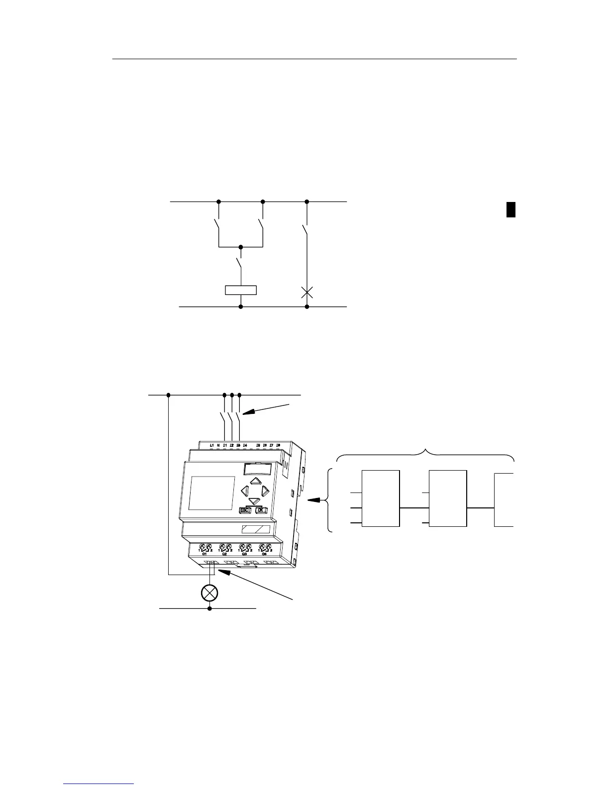
View of a circuit diagram
You know, of course, how a circuit logic is represented in a
circuit diagram. Nevertheless, here is an example:
K1
S1
K1
S2
E1
Load E1 is switched on and
off by means of the switches
(S1 OR S2) AND S3.
S3
Relay K1 picks up when
condition (S1 OR S2) AND S3
is met.
Creating this circuit with LOGO!
In LOGO! you create a circuit logic by interconnecting
blocks and connectors:
S1 ... S3
Wiring of the inputs
I3
x
Q1
&1
I1
I2
x
Circuit program in LOGO!
Wiring of the outputs
L
1
N
Pro