LOGO! Manual
A5E00380835-01
36
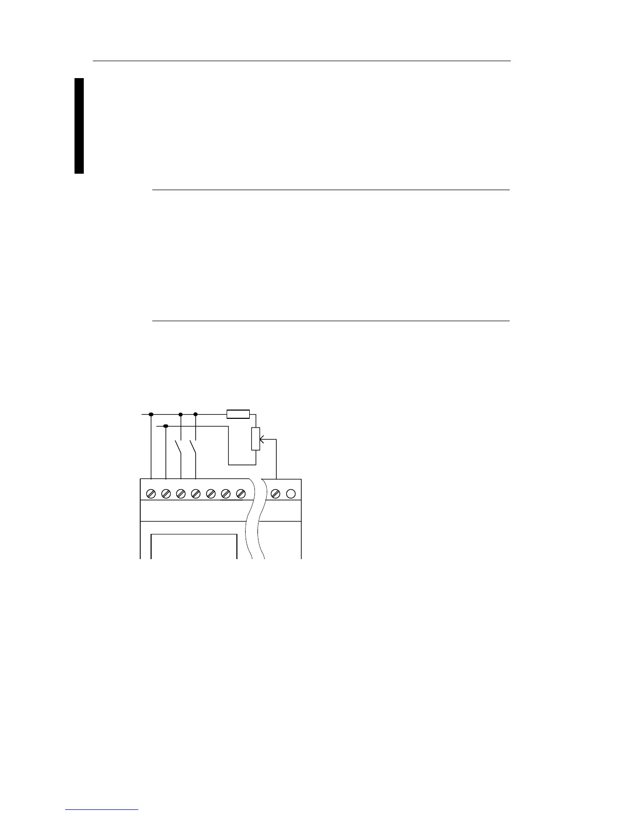
When using a potentiometer and 10 V input voltage as the
maximum value, you must ensure that with a connected
input voltage of 24 V, 14 V must release via the series resi-
stor so that a maximum of 10 V are supplied when you turn
the potentiometer one full rotation. With a voltage of 12 V,
this can be neglected.
Note
The LOGO! AM 2 expansion module provides further
analog inputs. The LOGO! AM 2 PT100 expansion module
provides Pt100 inputs.
Always use twisted and shielded cables for analog signals,
and keep these as short as possible.
Sensor connections
To connect sensors to the LOGO! :
LOGO! 12/24 ....
L+
M
The inputs of these devices not
isolated and therefore require a
common reference potential
(chassis ground ).
At the LOGO! 12/24RC/RCo and
LOGO! 24/24o modules, you can
tap analog signals between the
supply voltage and chassis ground
(* = series resistor with 24 V DC).
ML+ I1 I2 I3 I4 I5 I8
*)
LOGO! installation and wirin