55
LOGO! Manual
A5E00380835-01
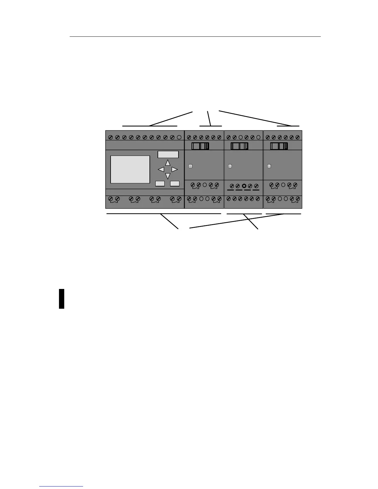
3.1 Connectors
The LOGO! is equipped with inputs and outputs
Example of a configuration with several modules:
L+ M I13I14I15I16
Q11
Q9
Q12
Q10
RUN/STOP
L+ M
A!3
RUN/STOP
L+MI1I2 I3I4I5I6
Q1 Q2 Q3 Q4
Inputs
Outputs
AI1 AI2 L+ M I9 I10 I11I12
Q7
Q5
Q8
Q6
RUN/STOP
M3U3AI4M4U4
Analog inputs
1 2 1
2
1 2 1 2
1 2 1 2 1 2 1 2
1 2 1 2
1 2 1 2
PE
INPUT 2x (..10 V/..20 mA)
L+ M
Each input is identified by the letter I plus a number. When
you look at the LOGO! from the front, you can see the input
terminals at the top. Only analog modules LOGO! AM 2
and AM 2 PT100 have the inputs at the bottom.
Each output is identified by the letter Q plus a number
(AM 2 AQ: V plus number). In the figure, you can see the
output terminals at the bottom.
Pro