LOGO! Manual
A5E00380835-01
72
Wiring
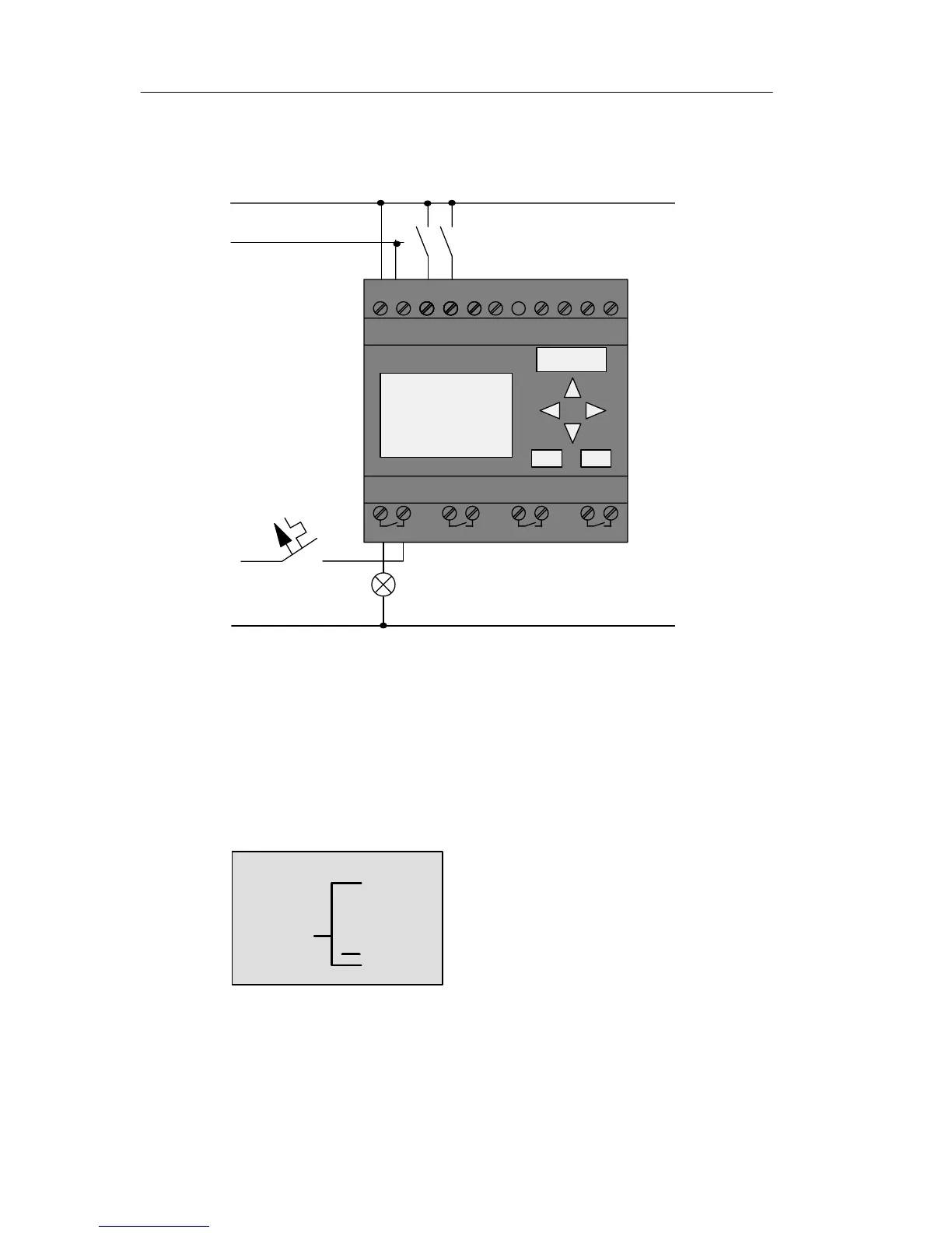
The corresponding wiring:
L1N I4 I5I6I7I8
Q1 Q2 Q3 Q4
L1
N
S1
S2
L
N
I1I1 I3I1I1 I1I1I1I2
1 2 1 2 1 2 1 2
S1 switches input I1, while S2 switches input I2. The load is
connected to the relay Q1.
3.7.3 Circuit program input
Let us now write the circuit program, starting at the output
and working towards the input. LOGO! initially shows the
output:
The first LOGO! output
Q1
Pro