33
LOGO! Manual
A5E00380835-01
Note
The digital inputs of LOGO! 230 RC/RCo and of expansion
module DM16 230R are divided into two groups, each
consisting of four inputs. Within the same group, all inputs
must be operated on the same phase. Different phases
are only possible between the groups.
Example:
I1 to I4 on phase L1, I5 to I8 on phase L2.
Inputs within the LOGO! DM8 230R may not be connected
to different phases.
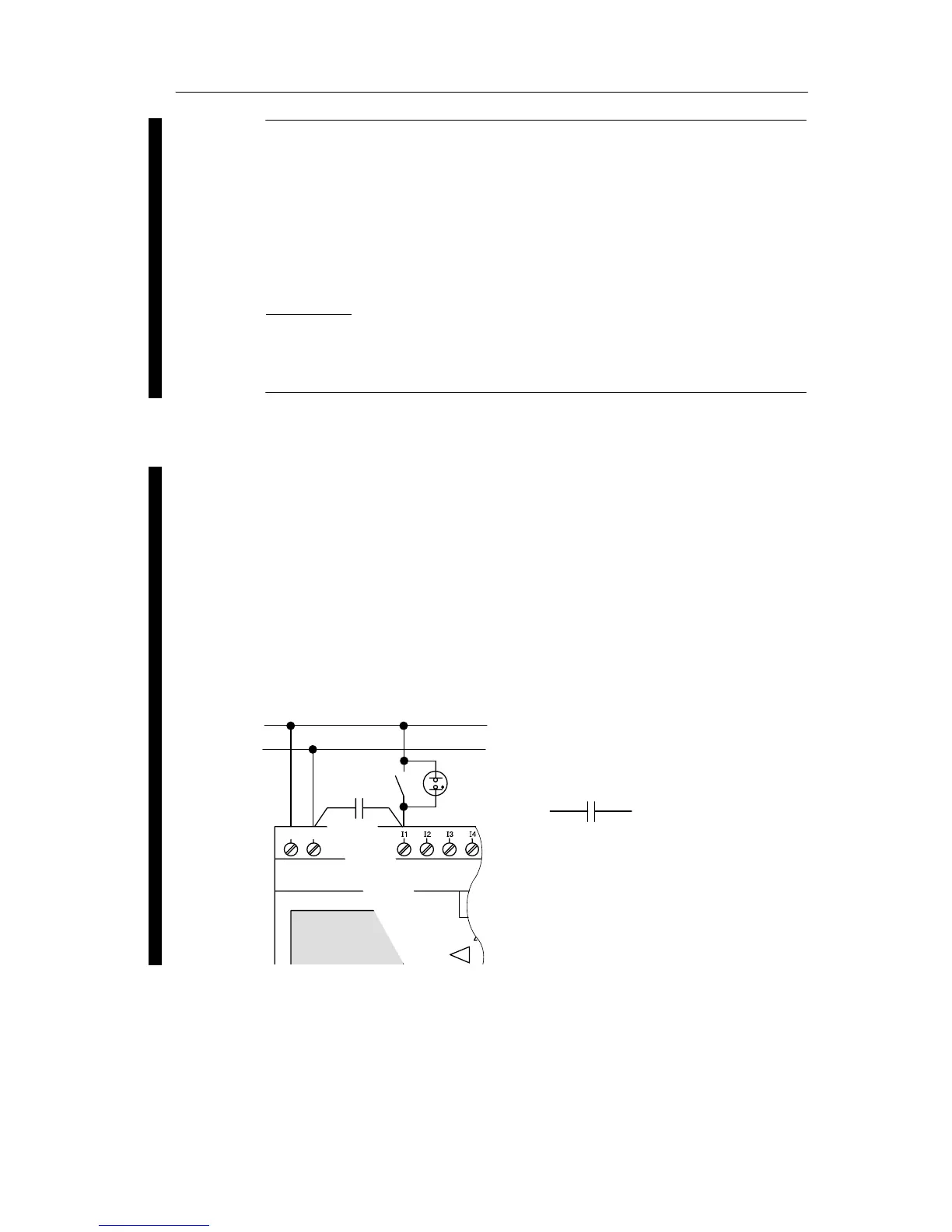
Sensor connections
Connecting glow lamps and 2-wire proximity switches
(Bero) to LOGO! 230 RC/230 RCo or LOGO! DM8 230 R
(AC) and LOGO! DM16 230R (AC)
The figure below shows how you connect a switch with a
glow lamp to the LOGO! The current that flows through the
glow lamp allows LOGO! to detect a ”1” signal even though
the switch contact is not closed. If, however, you use a
switch whose glow lamp is fitted with a power supply, this
response does not occur.
L1
N
NL1
C
3SB1420-3D
Order number for C:
Siemens
Switchgear & Systems
X-capacitor 2.5 kV, 100 nF
LOGO! installation and wirin