149
LOGO! Manual
A5E00380835-01
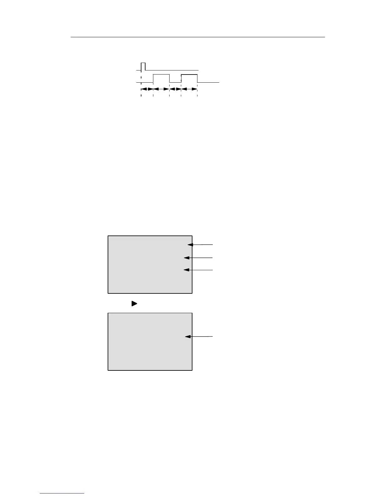
Timing diagram B
Trg
N=2
Q
T
L
T
H
T
L
T
H
T
L
T
H
T
L
T
H
Timing diagram for the sample
configuration
Functional description
A 0 to 1 transition at input Trg triggers the time T
L
(Time
Low). After the time T
L
has expired, output Q is set for the
duration of T
H
(Time High).
If there is a further 0 to 1 transition (retriggering pulse) at
input Trg before the preset time (T
L
+ T
H
) has expired, T
a
is
reset and the pulse/pause cycle is restarted.
If retentivity is not set, output Q and the time are reset after
a power failure.
Preset of the Par parameter
View in programming mode (example):
B25 1+R
TL =02:00s
TH =03:00s
Protection mode and retentivity
Interpulse width
Pulse width
Press
B25 2
N=1
Number of pulse/pause cycles
(example)
LOGO! functions