71
LOGO! Manual
A5E00380835-01
3.7.2 The first circuit program
Let us now take a look at the following parallel circuit con-
sisting of two switches.
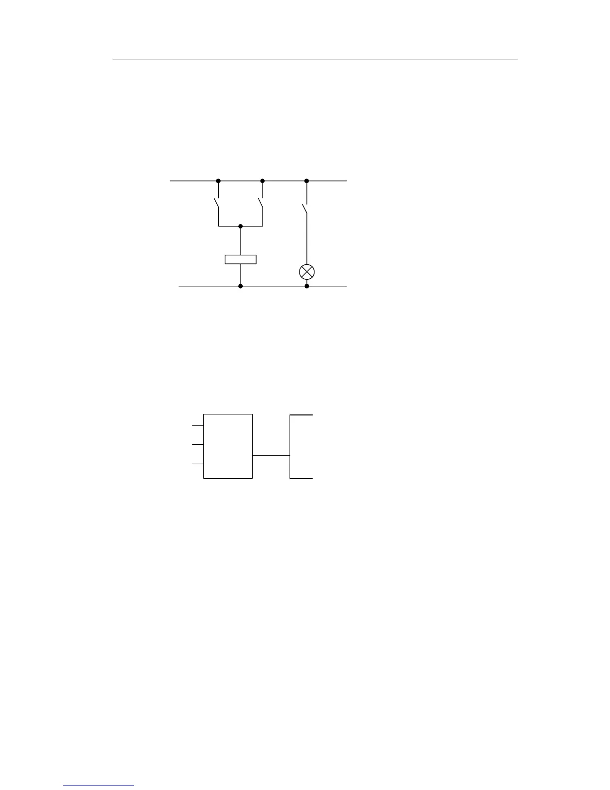
Circuit diagram
The corresponding circuit diagram:
K1
S1
K1
S2
E1
The load is switched on with
S1 OR S2. LOGO! interprets
this parallel circuit as an ’OR’
logic, because S1 OR S2
switches on the output.
Translated into a LOGO! circuit program this means: Relay
K1 is at output Q1 is controlled by means of an OR block.
Circuit program
S1 is connected to the I1 and and S2 to the I2 input con-
nector of the OR block.
The corresponding layout of the circuit program in LOGO!:
I1
I2
x
Q1
1
Pro