19
LOGO! Manual
A5E00380835-01
2.1 Setup of the modular LOGO!
2.1.1 Maximum setup
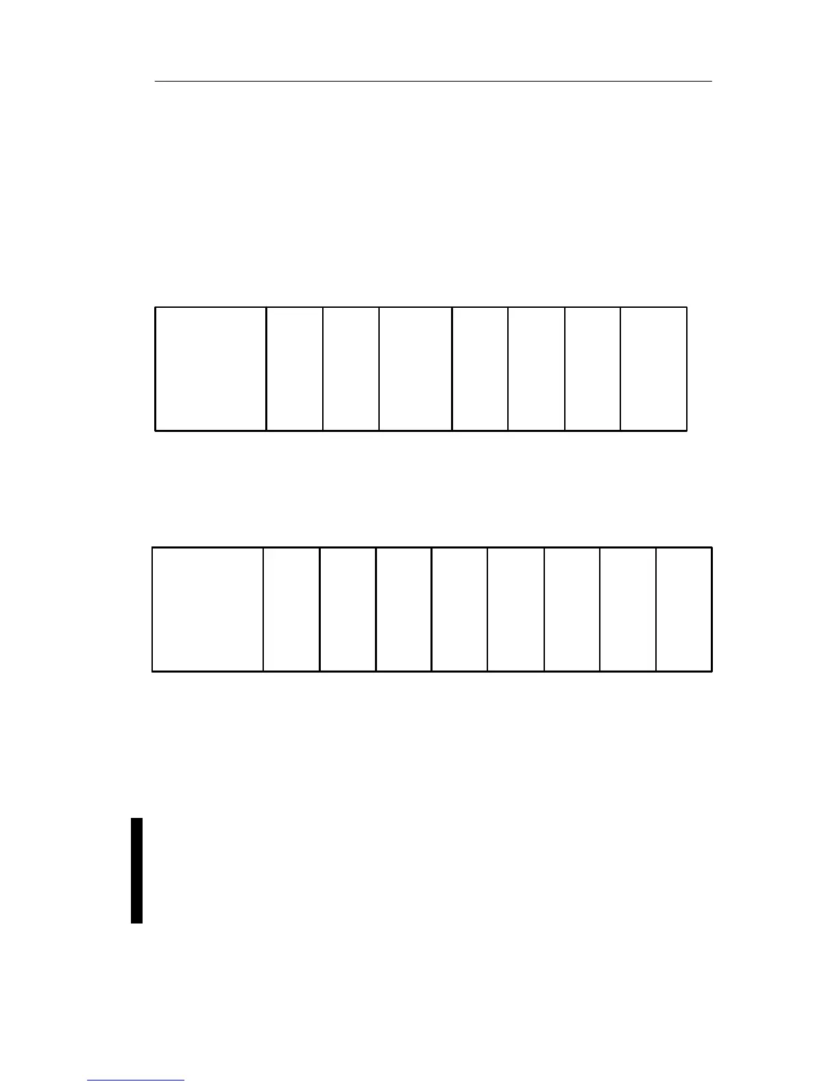
Maximum setup of a LOGO! with analog inputs
(LOGO! 12/24 RC/RCo and LOGO! 24/24o)
LOGO! Basic, 4 digital modules and 3 analog modules
LOGO! Basic
LOGO!
DM 8
LOGO!
DM 8
LOGO!
DM 8
LOGO!
DM 8
LOGO!
AM 2
LOGO!
AM 2
LOGO!
AM 2
I9...I12 I13...I16 I17...I20 I21...I24
AI3, AI4 AI5, AI6 AI7, AI8
I1......I6, I7, I8
AI1, AI2
Q1...Q4 Q5...Q8 Q9...Q12 Q13...Q16
Maximum setup of a LOGO! without analog inputs
(LOGO! 24 RC/RCo and LOGO! 230 RC/RCo)
LOGO! Basic, 4 digital modules and 4 analog modules
LOGO! Basic
LOGO!
DM 8
LOGO!
DM 8
LOGO!
DM 8
LOGO!
DM 8
LOGO!
AM 2
LOGO!
AM 2
LOGO!
AM 2
I9...I12 I13...I16 I17...I20 I21...I24
AI3, AI4 AI5, AI6 AI7, AI8
I1 . . . . . . . . . . . I8
AI1 , AI2
LOGO!
AM 2
Q1...Q4 Q5...Q8 Q9...Q12
Q13...
Q16
High-speed/optimal communication performance
For optimal and high-speed communication performance
between LOGO! Basic and the various modules, we
recommend you install the “digital modules first, then the
analog modules” (example above).
We recommend that you position the CM AS Interface on
the far right-hand side. (If the AS Interface voltage fails,
communication between the LOGO! system and the expan-
sion modules, which are arranged to the right of the LOGO!
CM AS Interface expansion module, is interrupted.)
LOGO! installation and wirin