Detailed description
2.6 Interface structure
Basic logic functions: PLC basic program solution line (P3 sl)
Function Manual, 11/2006, 6FC5397-0BP10-2BA0
37
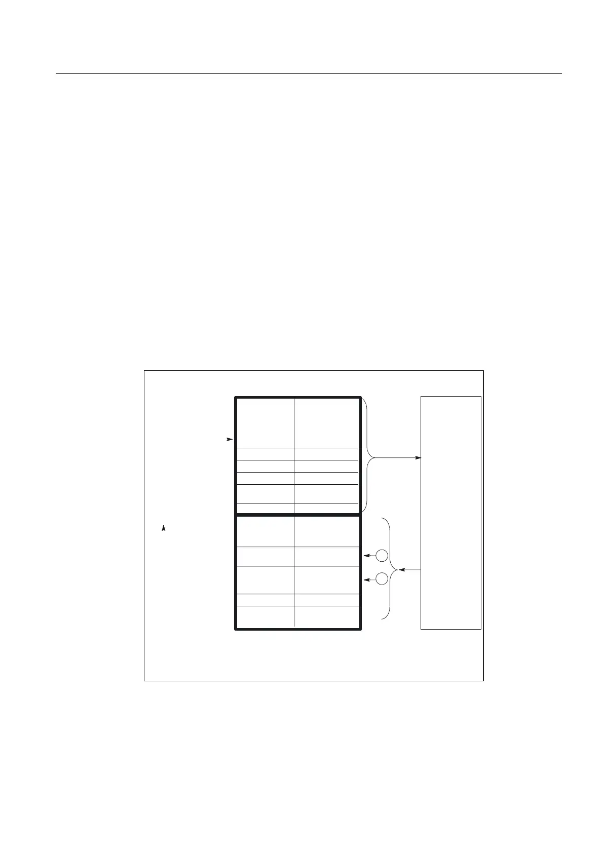
PLC/axis, spindle, drive signals
The axis-specific and spindle-specific signals are divided into the following groups:
• Shared axis/spindle signals
• Axis signals
• Spindle signals
• Drive signals
The signals are transmitted cyclically at the start of OB1 with the following exceptions:
Exceptions include:
• Axial F value
• M value
• S value
An axial F value is entered via the M, S, F distributor of the basic program if it is transferred
to the PLC during the NC machining process.
The M and S value are also entered via the M, S, F distributor of the basic program if one or
both values require processing.
%\WHV
'%
1&.
6WDWXVVLJQDOV
*ULQGLQJ
7HFKQRORJ\
&RQWUROVLJQDOV
5HVHUYH
YDOXHVRI06DQG)GLVWULEXWRUVRIEDVLFSURJUDP
$[LV
VSLQGOH
GULYH
6WDWXVVLJQDOV
06YDOXH
6WDWXVVLJQDOV
6HWJHDUVWHS
$[LDO)YDOXH
6WDWXVVLJQDOV
$FWLYH,1&PRGH
6WDWXVVLJQDOV
'ULYHVLJQDOV
6SLQGOH
VLJQDOV
$[LVVLJQDOV
6KDUHG
D[LVVSLQGOH
VLJQDOV
*ULQGLQJ
7HFKQRORJ\
&RQWUROVLJQDOV
'ULYHVLJQDOV
$[LVVLJQDOV
/LPLWVZLWFKHV
&RQWUROVLJQDOV6SLQGOHVLJQDOV
6KDUHG
D[LVVSLQGOH
VLJQDOV
7UDYHUVHVLJQDOV
&RQWUROVLJQDOV
)HHGUDWHVSLQGOH
RYHUULGH
Figure 2-8 Interface between PLC and axes/spindles/drives
 Loading...


