Detailed description
2.7 Program operation mode
Basic logic functions: Mode group, channel, program operation, reset response (K1)
138 Function Manual, 11/2006, 6FC5397-0BP10-2BA0
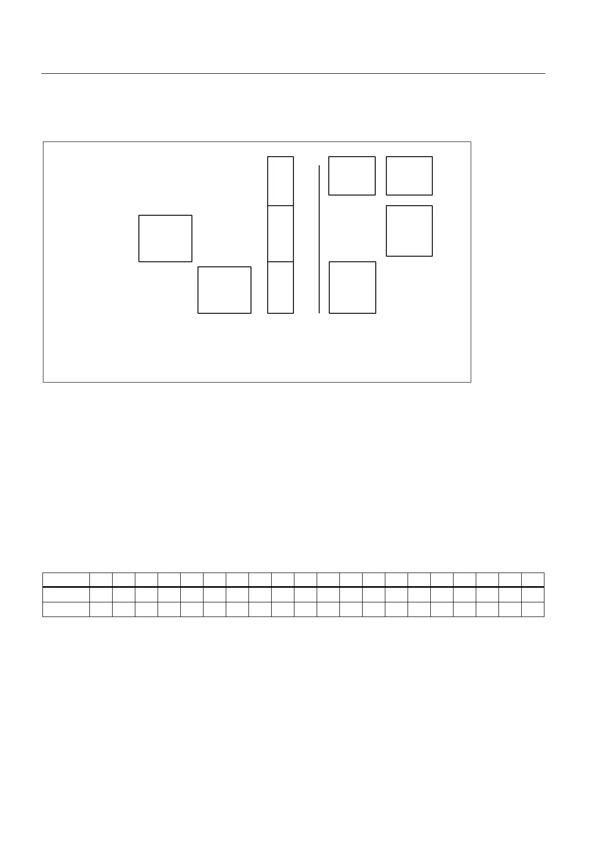
The following diagram illustrates which routines are used:
1
2
0
User
RET
User
REPOS
Value stored in MD 11610
_N_ASUP_SPF
System
ASUB
RET
System
ASUB
REPOS
System
ASUB
REPOS
System
ASUB
RET
NCK system SW
User SW
ASUP_EDITABLE
Figure 2-14 Replacing system ASUBs with user routines
Installation of user system ASUBs
One routine named _N_ASUP_SPF can be loaded in directory _N_CUS_DIR. You must
implement the actions desired by the user for:
RET for Value 1 in MD11610
REPOS for Value 2 in MD11610
Reason for activation of an ASUP and its significance
The reason that led to the activation is specified in bit code through the $AC_ASUP system
variable, and can be read in part program and synchronized actions.
Bit 19 18 17 16 15 14 13 12 11 10 9 8 7 6 5 4 3 2 1 0
RET 1 1 * 1
REPOS 1 1 1 1 1 1 1 1 * 1 1 1
On*): If Bit 9 is set, the branching of machine data depends on
MD20114 $MC_MODESWITCH_MASK (interrpution of MDA through mode change):
Bit 0 set: →RET
Bit 0 not set: →REPOS
 Loading...


