Detailed description
2.10 System settings for power-up, RESET/part-program end and part-program start
Basic logic functions: Mode group, channel, program operation, reset response (K1)
Function Manual, 11/2006, 6FC5397-0BP10-2BA0
171
Application
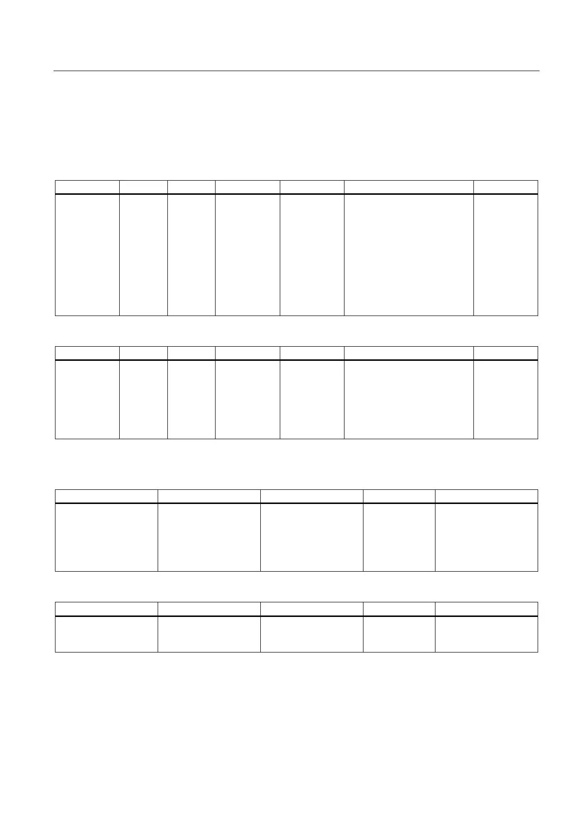
If a bit is set in MD20112 $MC_START_MODE_MASK, the reset action of the relevant
function can be delayed until the start of the part program.
Table 2-17 Effect of MD20112 $MC_START_MODE_MASK Bits 1 to 7
Bit 1 = 1 Bit 2 = 1 Bit 3 = 1 Bit 4 = 1 Bit 5 = 1 Bit 6 = 1 Bit 7 = 1
No D, T, M
output on tool
selection;
with active
tool
management
irrelevant
Reserved Reserved Plane
according to
MD20150
$MC_GCODE
_RESET_VAL
UES
Frame
according to
MD20150
$MC_GCODE
_RESET_VAL
UES
WZK according to
MD20120
$MC_TOOL_RESET_VALUE,
MD20121
$MC_TOOL_PRESEL_RESET
_
VALUE, and
MD20130 $MC_CUTTING_
EDGE_RESET_VALUE;
Output of D, T, M to PLC,
depending on bit 1
Transformatio
n according to
MD20140
$MC_TRAFO_
RESET_VALU
E
Bit 1 = 0 Bit 2 = 0 Bit 3 = 0 Bit 4 = 0 Bit 5 = 0 Bit 6 = 0 Bit 7 = 0
D, T, M output
on tool
selection;
with active
tool
management
irrelevant
Reserved Reserved Current plane
is retained
Current
settable frame
is retained
Active tool length offset is
retained
Active
transformation
is retained
Table 2-18 Effect of MD20112 $MC_START_MODE_MASK Bits 8 to 12
Bit 8 = 1 Bit 9 = 1 Bit 10 = 1 Bit 11 = 1 Bit 12 = 1
Coupledaxis groupings
are deactivated
Tangential follow-up is
deactivated
Not configured
synchronous spindle
coupling is switched off
Reserved Geometry axis
assignment is deleted
according to MD 20050,
depending on MD
20118 (because of
compatibility)
Bit 8 = 0 Bit 9 = 0 Bit 10 = 0 Bit 11 = 0 Bit 12 = 0
Coupledaxis groupings
are retained
Tangential follow-up is
retained
Not configured
synchronous spindle
coupling remains active
Reserved Modified geometry axis
assignment is retained
 Loading...


