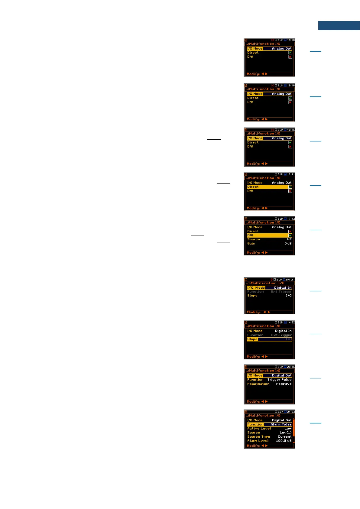
Screen that enables configuring the instrument's I/O port
parameters: I/O Mode, Direct, D/A, Function, Slope,
Polarisation, Active Level, Source, Source Type, Alarm
Level, Send SMS and Send E-Mail.
Detailed description of the I/O port is given in
Appendix C.
Mode of the I/O port: Analog Out, Digital In, Digital Out.
Mode of the I/O port when analogue signal is transmitted
from the input of the instrument to its output (pin 1 of the
I/O connector) without any digital processing (Direct) or
after digital-to-analogue converter (D/A).
Parameter that enables the measured signal from the
measurement channel to be transmitted to the pin 1 of
the I/O connector without any digital processing (filtering
and gaining).
Parameter that enables transmitting the analogue signal
from the internal signal generator of the instrument after
digital-to-analogue converter to the pin 1 of the I/O
connector, and the analogue input signal to the pin 2 of
the I/O connector after digital-to-analogue converter.
The input signal can be weighted with HP, Z, A, C or B
filter (Source) and additionally gained by -60 dB to 60 dB
(Gain).
Mode of the I/O port when external digital signal is used
as an external trigger to start measurements. The
instrument is acting in this case as so called “slave
instrument”.
Trigger voltage slope defined for the Digital In I/O mode:
[+] (uprising as default) or [–] (falling).
Mode of the I/O port when digital signal is used for
triggering other “slave instrument(s)” (the instrument is
acting in this case as a “master instrument”), or as a
source of alarm signal.
Functionality of the Digital Out I/O mode: Trigger Pulse
or Alarm Pulse.