TH2829X Series Operation Manual Chapter 10 HANDLER
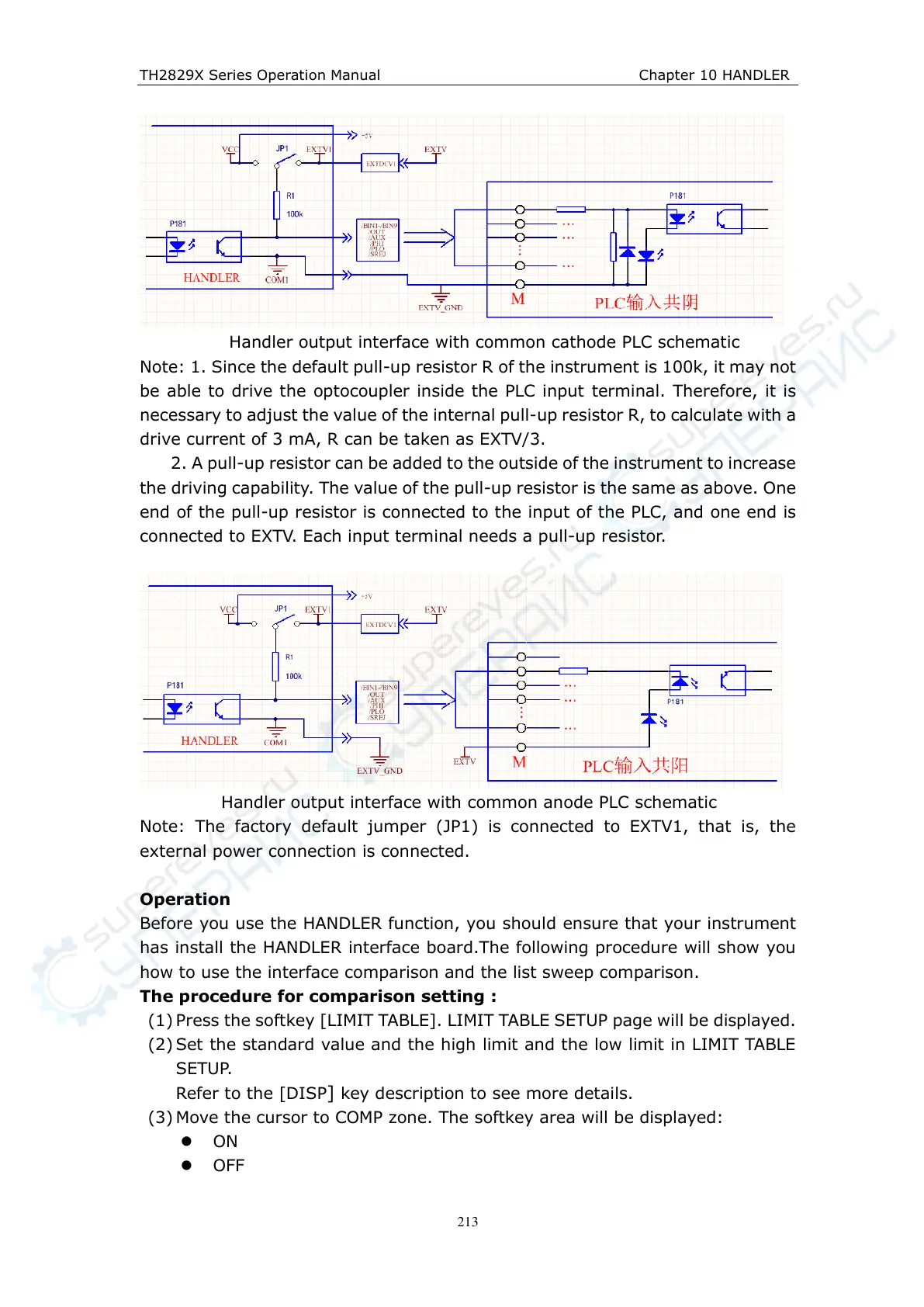
Handler output interface with common cathode PLC schematic
Note: 1. Since the default pull-up resistor R of the instrument is 100k, it may not
be able to drive the optocoupler inside the PLC input terminal. Therefore, it is
necessary to adjust the value of the internal pull-up resistor R, to calculate with a
drive current of 3 mA, R can be taken as EXTV/3.
2. A pull-up resistor can be added to the outside of the instrument to increase
the driving capability. The value of the pull-up resistor is the same as above. One
end of the pull-up resistor is connected to the input of the PLC, and one end is
connected to EXTV. Each input terminal needs a pull-up resistor.
Handler output interface with common anode PLC schematic
Note: The factory default jumper (JP1) is connected to EXTV1, that is, the
external power connection is connected.
Operation
Before you use the HANDLER function, you should ensure that your instrument
has install the HANDLER interface board.The following procedure will show you
how to use the interface comparison and the list sweep comparison.
The procedure for comparison setting :
(1) Press the softkey [LIMIT TABLE]. LIMIT TABLE SETUP page will be displayed.
(2) Set the standard value and the high limit and the low limit in LIMIT TABLE
SETUP.
Refer to the [DISP] key description to see more details.
(3) Move the cursor to COMP zone. The softkey area will be displayed:
ON
OFF