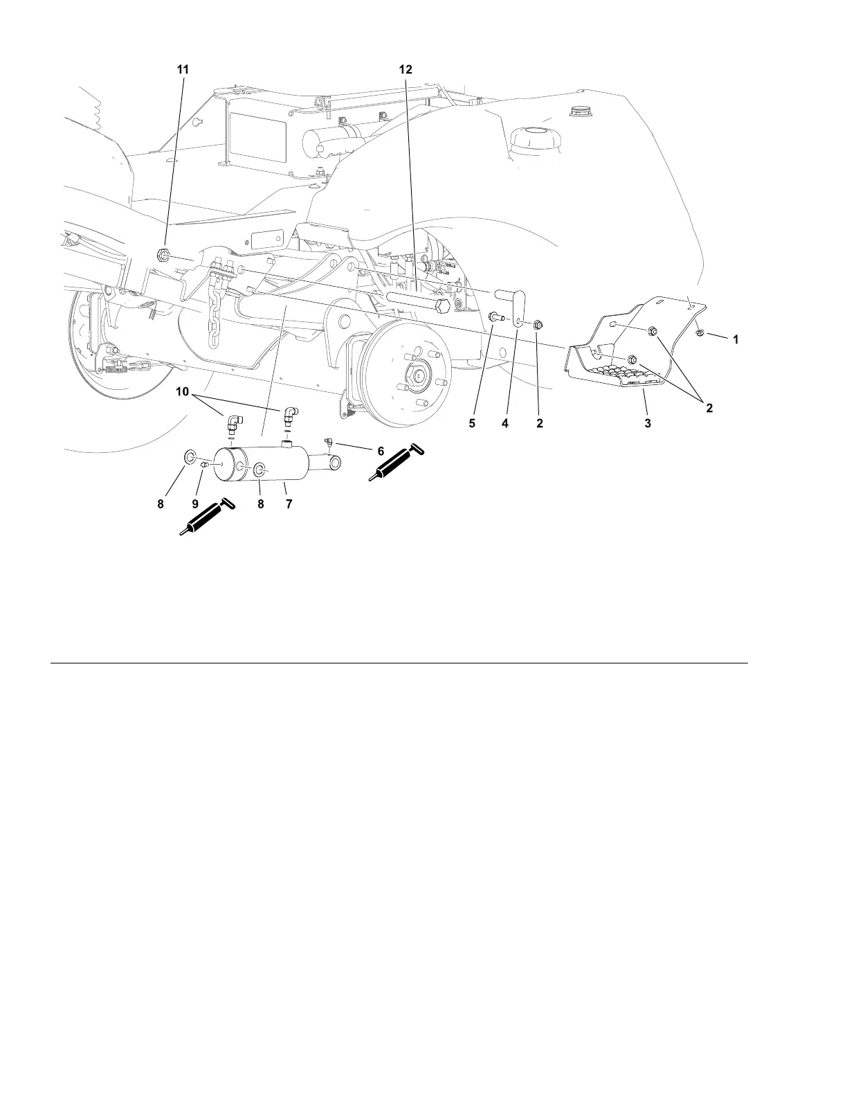
LiftCylinder
g303516
Figure70
1.Flangenut(2each)5.Capscrew9.Greasetting
2.Flangenut(3each)6.Greasetting10.Elbowtting(2each)
3.Step7.Liftcylinder
11.Locknut
4.Pivotpin
8.Nylonwasher(2each)
12.Pivotbolt
RemovingtheLiftCylinder
RefertoFigure70forthisprocedure.
1.Removethefrontwheeltoaccesstheliftcylinderpivotpins;referto
RemovingandInstallingtheWheels(page7–5).
2.Toaccesstheleftliftcylinder,removethestepassembly.
3.Supportthecuttingunitorliftarm.
4.Removethenut,pivotbolt,andnylonwasherssecuringthebarrelendofthe
cylindertotheframe.
5.Removethepivotpinsecuringtherodendofthecylindertotheliftarmand
lowerthecylindertoaccessthehydraulicttings.
6.ReadandadheretotheinformationprovidedinGeneralPrecautionsfor
RemovingandInstallingtheHydraulicSystemComponents(page5–52).
7.Cleanthettingandhydraulichoseconnectionsbeforedisconnectingthe
hydraulichosestopreventsystemcontamination.
8.Disconnectthehydraulichoses.Capthettingsandplugthehosesto
preventsystemcontamination.
HydraulicSystem:ServiceandRepairs
Page5–102
Groundsmaster
®
3200,3300and3310
19240SLRevA
 Loading...


