AuxiliaryHydraulicValveManifold(optional)
g303669
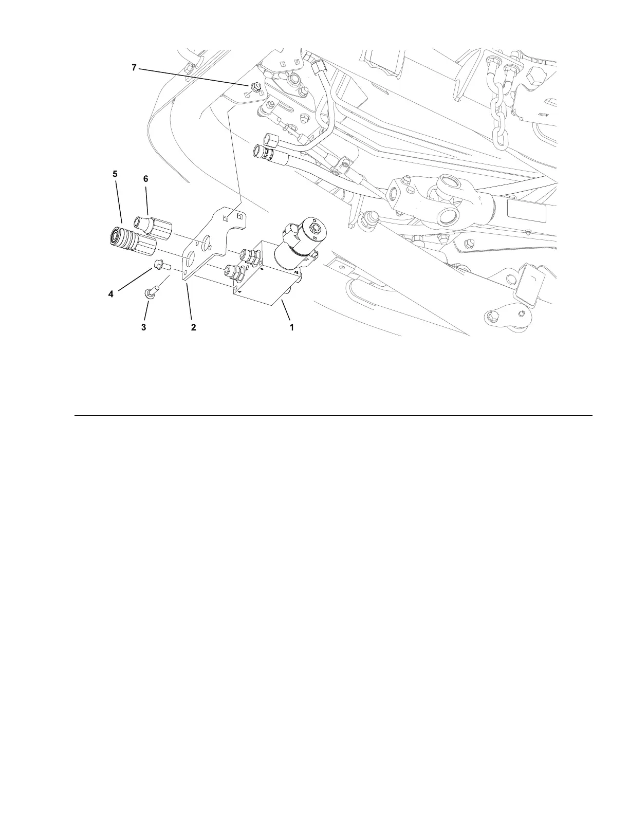
Figure72
1.Valvemanifoldassembly4.Capscrew(3each)7.Locknut(2each)
2.Bracket
5.Quickdisconnecttting–female
3.Carriagebolt(2each)6.Quickdisconnecttting–male
Anoptionalauxiliaryhydraulicvalvekitisavailable.Thekitisintendedtoexpand
thehydrauliccapabilityforfrontmountedattachments.Thekitincludesadual
coilcartridgestylesolenoidvalvecontrolledbyapanelmountedswitch.The
cartridgevalvemanifoldislocatedatthefrontrightsideofthemachineunder
theoperatorplatform.
RemovingandInstallingtheAuxiliaryHydraulicValveManifold
1.Parkthemachineonalevelsurface,lowerthecuttingunit(orattachment),
engagetheparkingbrake,setthekeyswitchtotheOFFpositionandremove
thekeyfromthekeyswitch.
2.Labelanddisconnectwireharnessconnectorsfromthecartridgevalve
solenoids.
3.Topreventcontaminationofhydraulicsystemduringmanifoldremoval,
thoroughlycleanexteriorofmanifold,hoseconnections,andttings.
4.Labelanddisconnectthehydrauliclinesfrommanifoldandputcapsorplugs
onopenhydrauliclinesandttingstopreventsystemcontamination.
5.Removethefastenerssecuringthemanifoldbrackettothemachineand
removethemanifoldassembly.
6.Installthemanifoldinreverseorder.
7.Removethecapsandplugsfromthettingsandhoses.Properlyconnect
thehydrauliclinestothemanifold;refertoInstallingHydraulicHosesand
Tubes(O-RingFaceSealFitting)(page5–7).
8.Connectthewireharnessconnectorstothecartridgevalvesolenoids.
Groundsmaster
®
3200,3300and3310
Page5–105
HydraulicSystem:ServiceandRepairs
19240SLRevA