ENGINE
4-116 Rev. 000 TX525 Service Manual
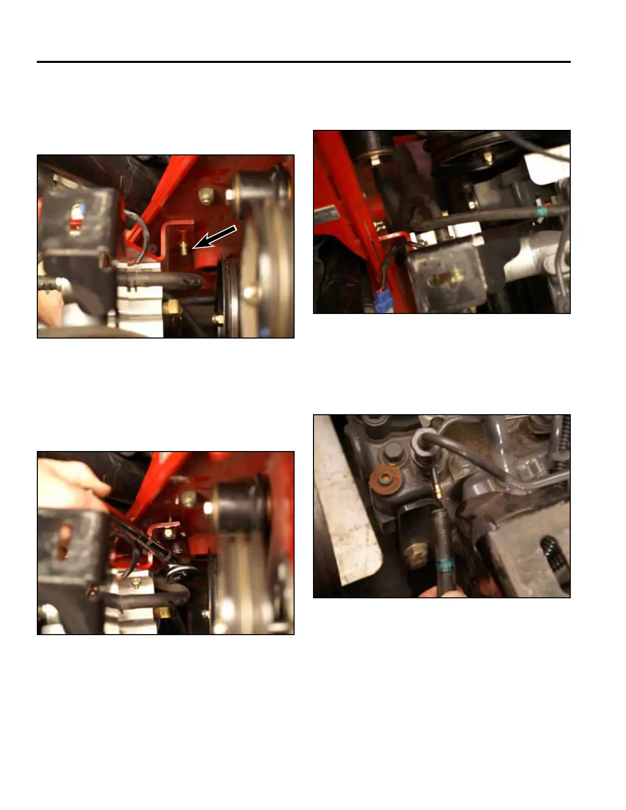
23. Positionthefuelpumpandlterassemblytothe
engine.Slidethefuelpumpmountingbracket
(bottommountinghole)ontotheboltthatwasleftin
thetowerassemb-lyuponremoval(Fig.0516).
Fig 0516 PICT-5580
24. Usinga1/2”socket,installthetopboltandnutand
thenutontothebottomboltsecuringthefuelpump
andlterbrackettothetowerframe(Fig.0517).
Fig 0517 PICT-5581
25. Routethefuelreturnlineupinbetweenthefuel
pumplinestothefuelinjector(Fig.0518).
Fig 0518 PICT-5582
26. Slidethefuelreturnlineontothefuelinjector(Fig.
0519).
Fig 0519 PICT-5472