ENGINE
4-137TX525 Service Manual Rev. 000
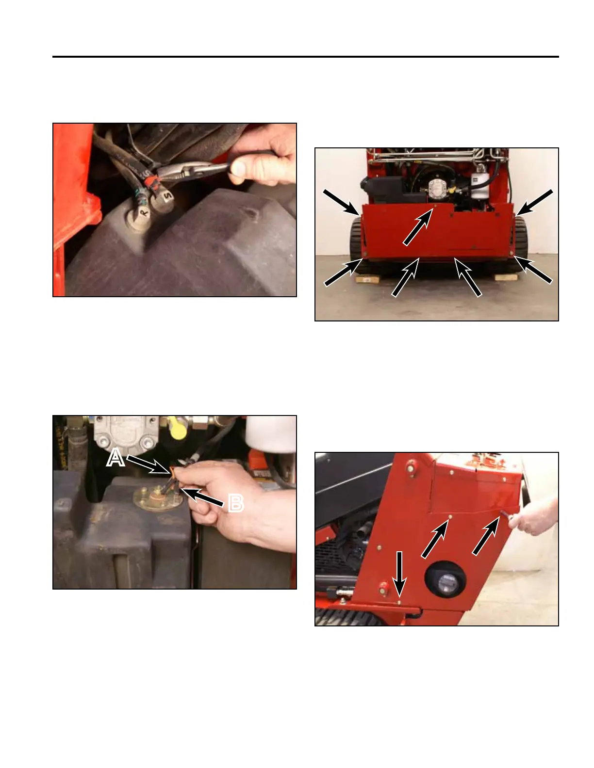
102. Positionthe2fuelhoseclampstosecurethefuel
linestothefueltankttings(Fig.0599).
Fig 0599 PICT-4264
103. Positionthefueltankintotherearoftheframe.
Connectthetwowires(blackandorange)tothe
fuelsendingunitlocatedonthetopofthefueltank
(Fig.0600).
Fig 0600 PICT-4262a
A. Centerterminal(orangewire)
B. Outsideterminal(blackwire)
A
B
104. Positiontherearframecovertotherearofthe
frame.Using3/4”and1/2”sockets,install7bolts
andnutstosecuretherearframecovertothe
frameandfueltankbracket(Fig.0601).
Fig 0601 PICT-5381
105. Positionthelefthandrearcoversupportpanelto
thetower.Usinga3/8”socket,install3screws
tosecuretheleftrearcoversupportpaneltothe
towerassembly.Repeattoinstalltherighthand
rearcoversupportpanel(Fig.0602).
Fig 0602 PICT-4256