ENGINE
4-173TX525 Service Manual Rev. 000
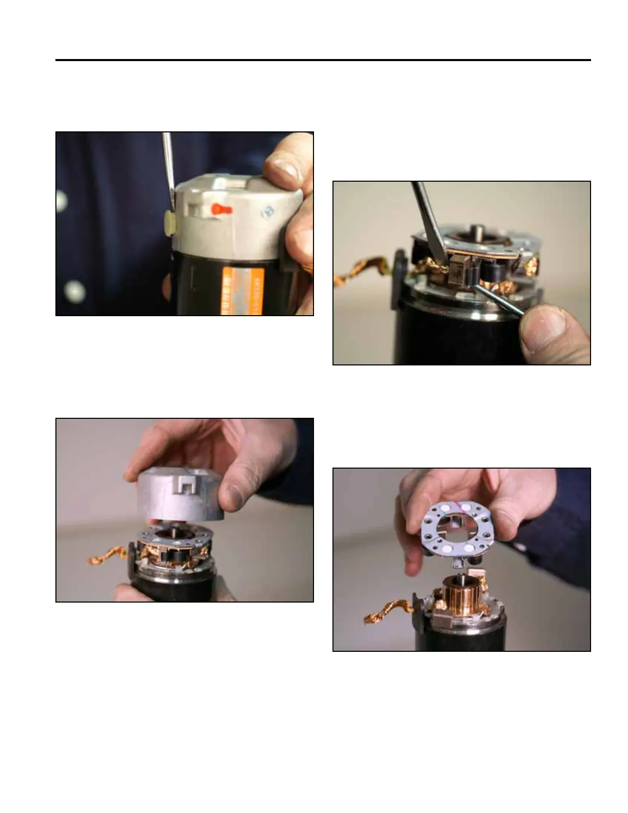
8. Removethecoverfromtheframeassembly(Fig.
0732).
10. Pullthespringsbackandslidethe2positive
brushesoutofthespringholderassembly(Fig.
0734).
Note: The positive brushes have leads attached to
the yoke.
Fig 0732 PICT-8144
Fig 0734 PICT-8040
11. Slidethebrushholderofftheyokeassembly(Fig.
0735).
9. Removetheframeassemblyfromthestarteras-
sembly(Fig.0733).
Fig 0735 PICT-8041a
Fig 0733 PICT-8034a