HYDRAULIC SYSTEM
6-2 Rev. 000 TX525 Service Manual
Fig 0835 PICT-4505a
4. Remove the rear access panel (Fig. 0835).
5. Using a 3/8” socket, remove the 3 screws securing
the right hand side support bracket to the tower.
Remove the right hand side support bracket (Fig.
0836).
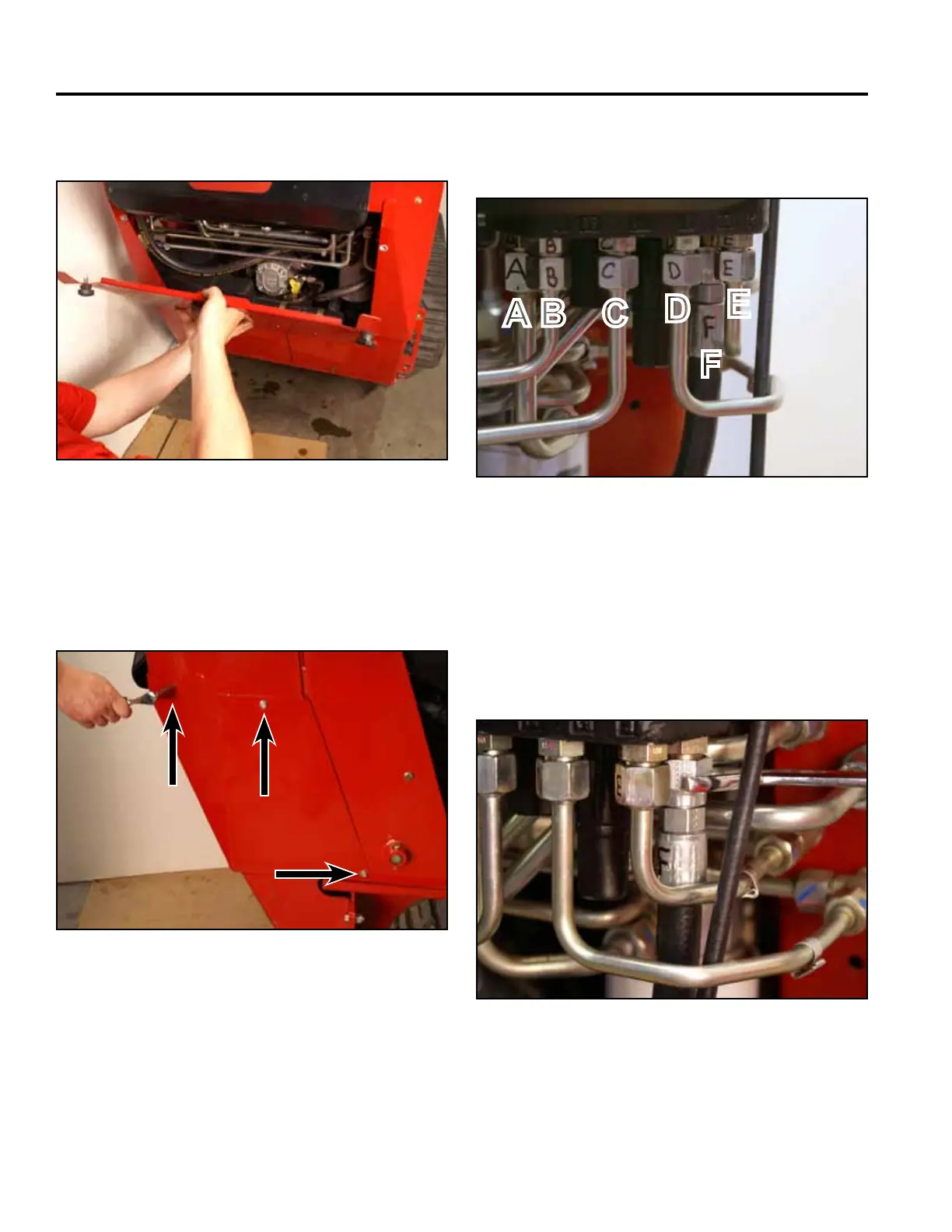
7. Using a 15/16” wrench, disconnect the hydraulic line
marked F from the 2 spool loader valve tting (Fig.
0838).
A. Hydraulic oil inlet line D. Hydraulic oil return line
B. Tilt cylinder line E. Lift cylinder line
C. Lift cylinder line F. Tilt cylinder line
Fig 0836 PICT-4504
Fig 0838 PICT-4879
6. Mark the 2 spool valve ttings and hydraulic line nuts
with the letters A – F as follows (Fig. 0837):
Fig 0837 PICT-4876a
A B C
D
F
E