HYDRAULIC SYSTEM
6-4 Rev. 000 TX525 Service Manual
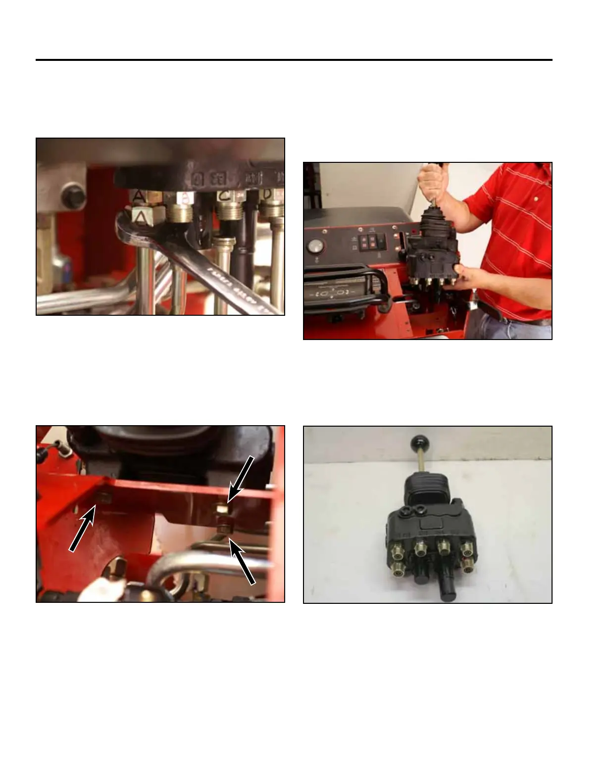
12. Using a 15/16” offset wrench, disconnect the hy-
draulic line marked A from the 2 spool loader valve
tting (Fig. 0843).
Fig 0843 PICT-4886
13. Using a 1/2” wrench and socket, remove the 3
mounting bolts and lock washers that secure the 2
spool loader valve to the control panel (Fig. 0844).
Fig 0844 PICT-4888
14. Remove the 2 spool loader valve from the control
panel assembly (Fig. 0845).
Note: Capallthehydrauliclinesandttingssothat
debris does not enter the system.
Fig 0845 PICT-4896
2 Spool Loader Valve (Fig. 0846).
Fig 0846 PICT-1749a