HYDRAULIC SYSTEM
6-8 Rev. 000 TX525 Service Manual
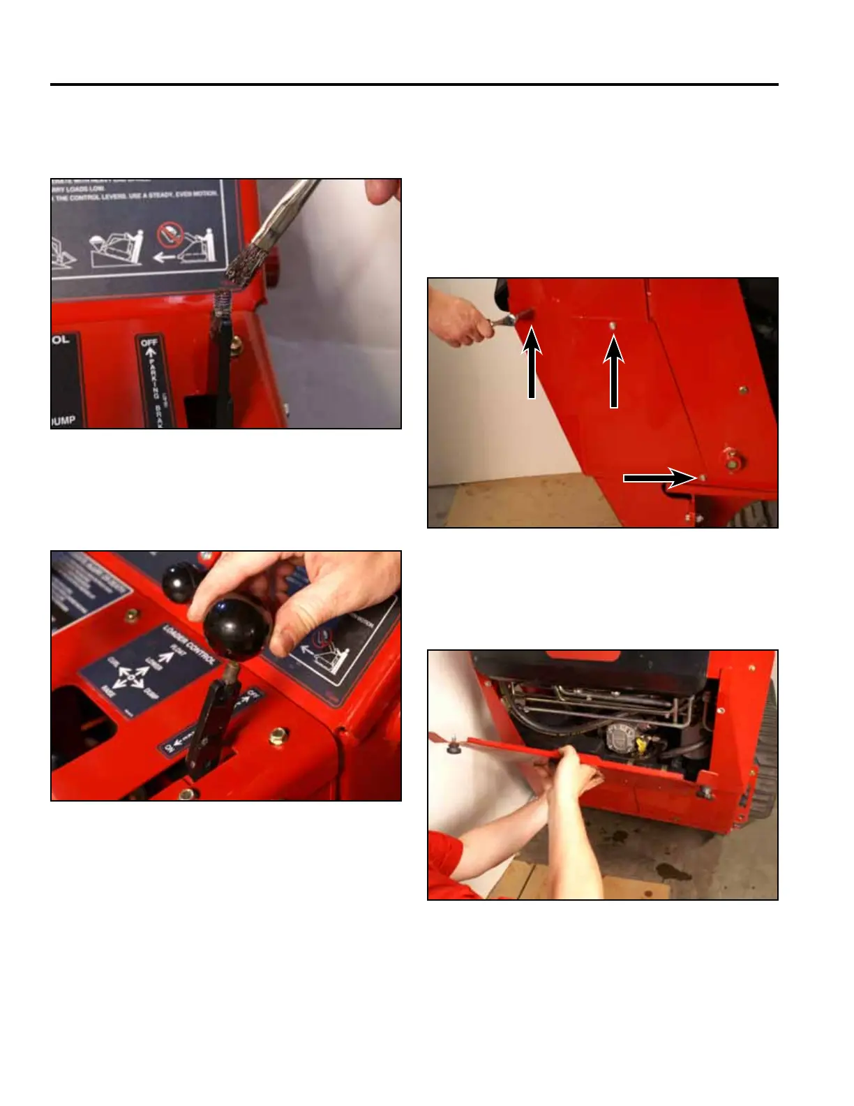
12. Apply thread locking compound (Loctite 416 or
equivalent) to brake handle threads (Fig. 0858).
Fig 0858 PICT-5526
13. Install the knob onto the brake handle (Fig. 0859).
Fig 0859 PICT-4342
14. Purge air from the hydraulic system. Refer to “Purg-
ing Air Procedure”, on page 9-19. Check for any
leaks in the hydraulic ttings and hydraulic hoses.
15. Position the right hand rear cover support panel
to the tower. Using a 3/8” socket, install 3 screws
to secure the right rear cover support panel to the
tower assembly (Fig. 0860).
Fig 0860 PICT-4504
16. Install the rear access panel (Fig. 0861).
Fig 0861 PICT-4505a