HYDRAULIC SYSTEM
6-7TX525 Service Manual Rev. 000
8. Using a 13/16” wrench, connect the hydraulic line
marked E to the 2 spool loader valve tting marked
E (Fig. 0854).
Fig 0854 PICT-4880a
9. Using a 15/16” wrench, connect the hydraulic line
marked F to the 2 spool loader valve tting marked F
(Fig. 0855).
Fig 0855 PICT-4879
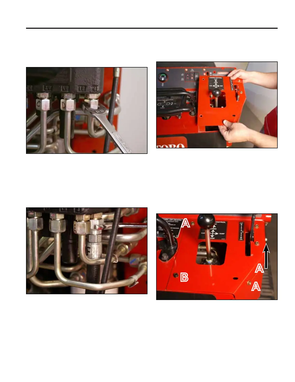
10. Position the right panel onto the control panel as-
sembly (Fig. 0856).
A. Self-tapping screw (3) B. Bolt and nut
Fig 0856 PICT-4343
11. Using a 3/8” socket, install 3 self-tapping screws that
secure the right panel to the control panel assembly.
Using a 3/8” socket and a 7/16” socket, install a bolt
and nut securing the lower left corner of the right
panel to the control panel assembly (Fig. 0857).
Fig 0857 PICT-4341
A
A
A
B