HYDRAULIC SYSTEM
6-12 Rev. 000 TX525 Service Manual
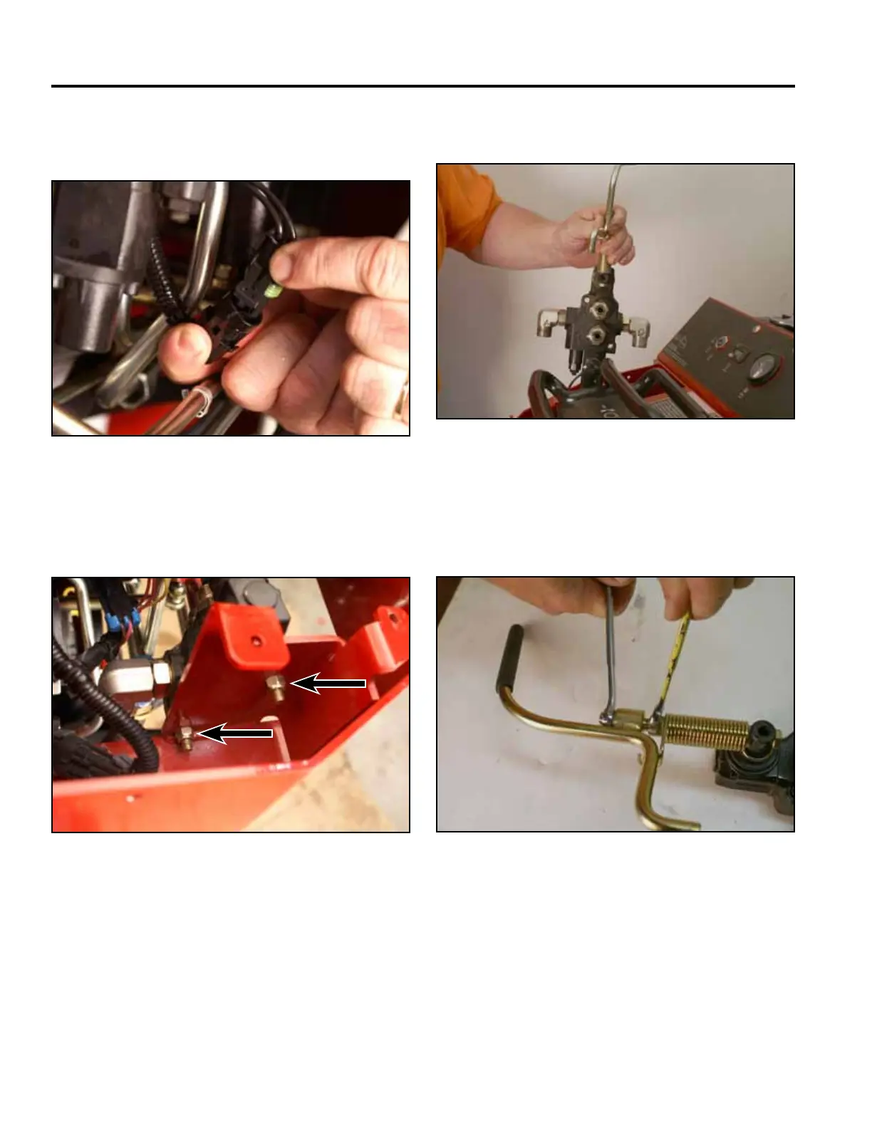
13. Disconnect the safety switch from the wire harness
(Fig. 0873).
Fig 0873 PICT-4910
14. Using a 1/2” socket and wrench, remove the 2
auxiliary valve mounting bolts and nuts (Fig. 0874).
Fig 0874 PICT-4912
15. Lift the valve out of the frame (Fig. 0875).
Fig 0875 PICT-4913a
16. Using two 7/16” wrenches, remove the top nut and
washer securing the handle to the hio spacer (Fig.
0876).
Fig 0876 PICT-1779a