HYDRAULIC SYSTEM
6-18 Rev. 000 TX525 Service Manual
16. Disengage the park brake and start the unit. Follow
the procedures for “Purging Air Procedure” on page
9-19. Check for any leaks at the hydraulic ttings
and in the hydraulic hoses.
17. If a new valve has been installed, perform a pres-
sure test. Refer to “Auxiliary Circuit Pressure Test”
on page 9-4.
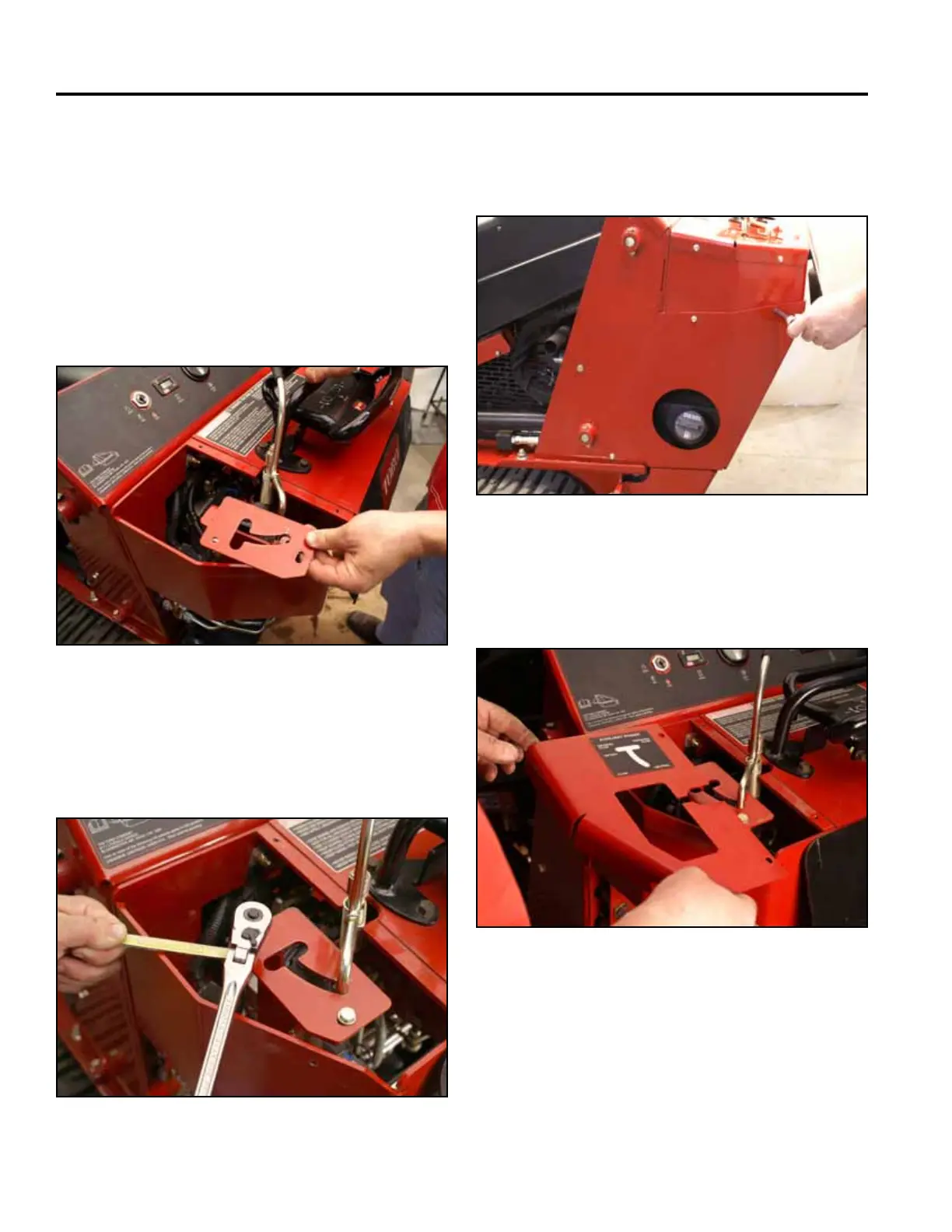
18. Position the stop plate over the auxiliary valve (Fig.
0897).
Fig 0897 PICT-4899
19. Using a 7/16” socket and wrench, install 2 bolts,
washers and nuts to secure the stop plate to the
control panel (Fig. 0898).
Fig 0898 PICT-4898a
20. Position the left side support panel. Using a 3/8”
socket, install 3 screws securing the left side support
panel to the tower assembly (Fig. 0899).
Fig 0899 PICT-4256
21. Position the top left panel onto the control panel (Fig.
0900).
Fig 0900 PICT-4601