HYDRAULIC SYSTEM
6-17TX525 Service Manual Rev. 000
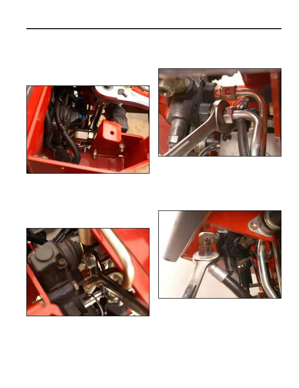
11. Remove the protective caps from the hydraulic lines
and ttings.
12. Using a 1-1/8” wrench, install the hydraulic line
marked with a D to the valve tting marked with a D
(Fig. 0893).
Fig 0893 PICT-4909
13. Using a 15/16” wrench, install the hydraulic line nut
marked with a C onto the valve tting marked with a
C (Fig. 0894).
Fig 0894 PICT-4906
14. Using a 15/16” wrench, install hydraulic line nut
marked with a B onto the valve tting marked with a
B (Fig. 0895).
Fig 0895 PICT-4904a
15. Using a 1-1/8” wrench, install the hydraulic line
marked with an A to the hydraulic tting marked with
an A (Fig. 0896).
Fig 0896 PICT-4903a