HYDRAULIC SYSTEM
6-26 Rev. 000 TX525 Service Manual
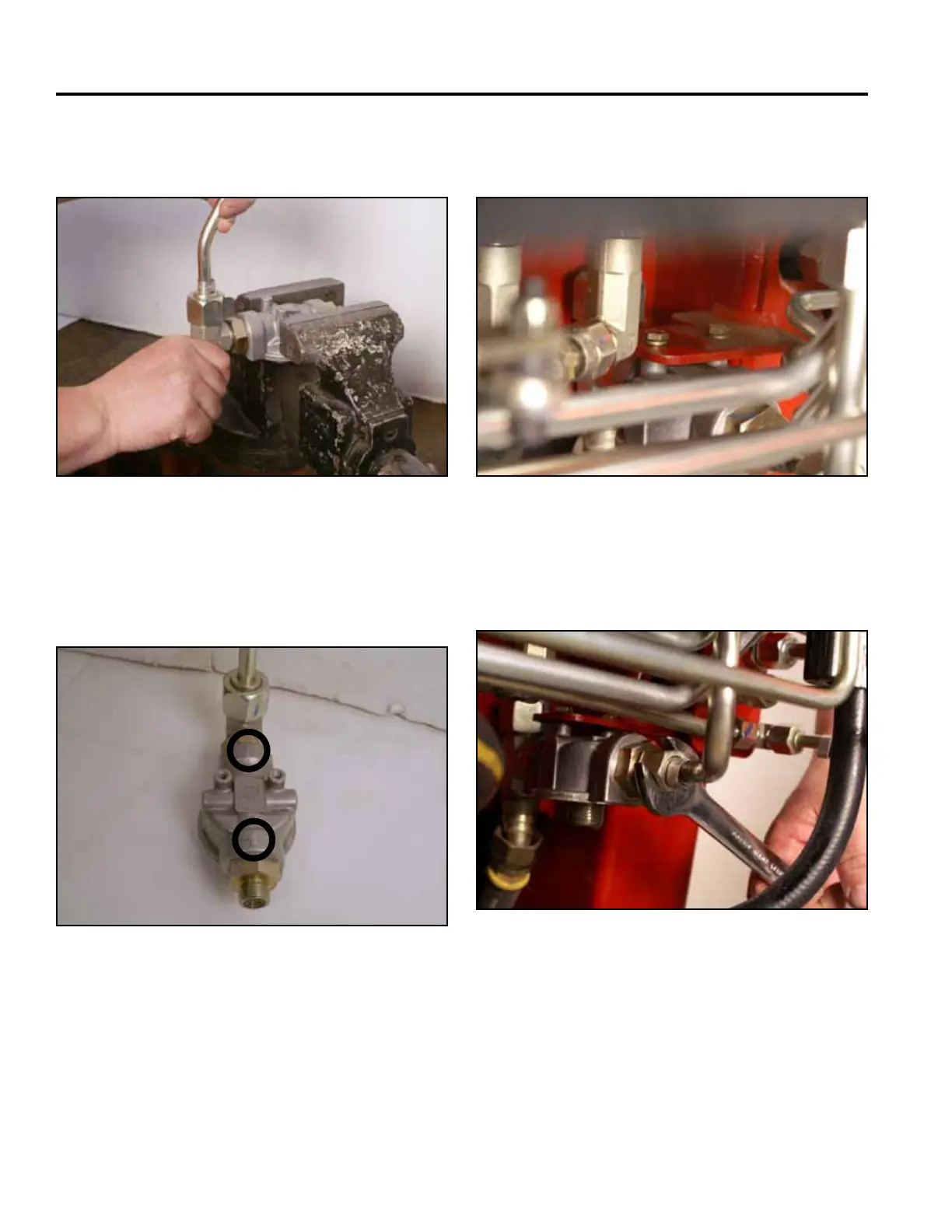
3. Thread the T-tting into the lter head – leave the
tting nut loose (Fig. 0927).
5. Install 2 bolts and washers securing the lter head
assembly to the mounting bracket (Fig. 0929).
Fig 0927 PICT-4938a Fig 0929 PICT-4924a
6. Using a 15/16” wrench, install the loader valve
hydraulic return line to the lter head (Fig. 0930).
4. Position the lter head assembly into the machine
so that the ow arrow points toward the front of the
machine (Fig. 0928).
Fig 0930 PICT-4923
Fig 0928 PICT-4940a