HYDRAULIC SYSTEM
6-27TX525 Service Manual Rev. 000
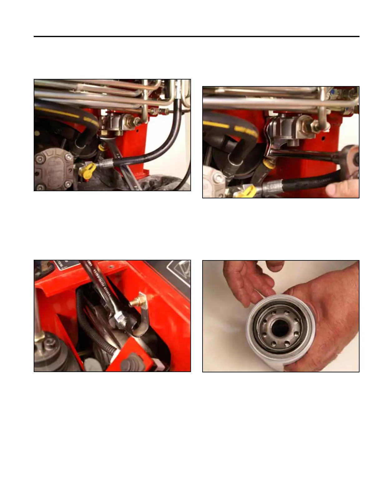
7. Using a 1-3/8” wrench, install the hydraulic reservoir
return line to the lter head T-tting (Fig. 0931).
9. Using a 1-3/8” wrench, tighten the T-tting nut se-
curing the T-tting to the lter head assembly (Fig.
0933).
Fig 0931 PICT-4919
Fig 0933 PICT-4941
10. Apply hydraulic uid to the gasket of the new
hydraulic lter (Fig. 0934).
8. Using a 15/16” wrench, install the hydrostatic pump
return line to the T-tting on the right hand pump
(Fig. 0932).
Fig 0934 PICT-4942
Fig 0932 PICT-4922