HYDRAULIC SYSTEM
6-28 Rev. 000 TX525 Service Manual
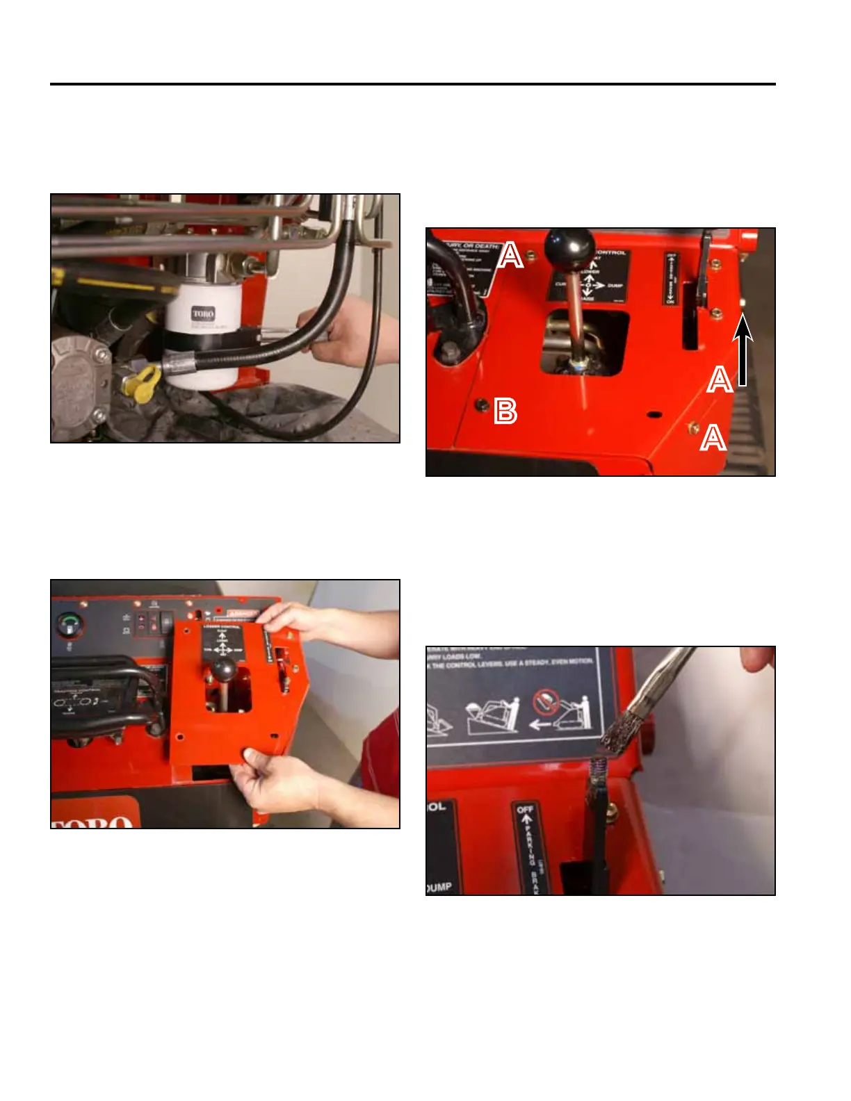
11. Install the new hydraulic oil lter onto the lter head:
Turn the lter until the gasket contacts the lter head
then tighten an additional 3/4 turn (Fig. 0935).
13. Using a 3/8” socket, install 3 self-tapping screws that
secure the right panel to the control panel assembly.
Using a 3/8” socket and a 7/16” socket, install a bolt
and nut securing the lower left corner of the right
panel to the control panel assembly (Fig. 0937).
Fig 0935 PICT-4943a
Fig 0937 PICT-4341
14. Apply thread locking compound (Loctite 416 or
equivalent) to brake handle threads (Fig. 0938).
A. Self-tapping screw (3) B. Bolt and nut
12. Position the right panel onto the control panel as-
sembly (Fig. 0936).
Fig 0938 PICT-5526
Fig 0936 PICT-4343a
A
A
A
B