HYDRAULIC SYSTEM
6-29TX525 Service Manual Rev. 000
19. Lower the machine.
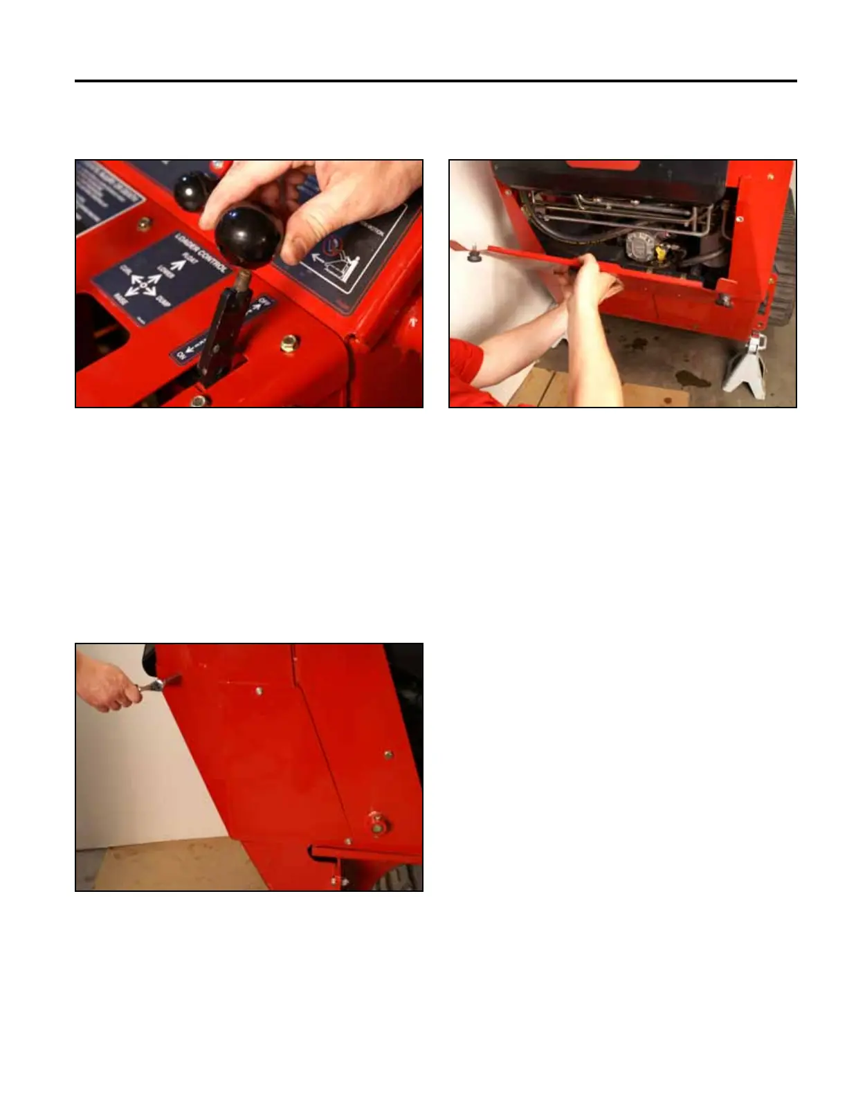
15. Install the knob onto the brake handle (Fig. 0939). 18. Install the rear access panel (Fig. 0941).
Fig 0939 PICT-4342
Fig 0941 PICT-4505
16. Purge air from the hydraulic system. Refer to “Purg-
ing Air Procedure”, page 9-19. Check for any leaks
in the hydraulic ttings and hydraulic hoses.
17. Position the right hand rear cover support panel
to the tower. Using a 3/8” socket, install 3 screws
to secure the right rear cover support panel to the
tower assembly (Fig. 0940).
Fig 0940 PICT-4504