HYDRAULIC SYSTEM
6-31TX525 Service Manual Rev. 000
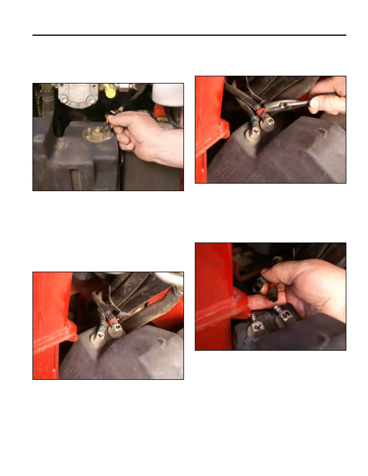
5. Disconnect the two wires (black and orange) from
the fuel sending unit located on the top of the fuel
tank (Fig. 0945).
7. Slide the 2 fuel hose clamps down the fuel line away
from the fuel tank ttings (Fig. 0947).
Fig 0945 PICT-4262a
Fig 0947 PICT-4264
8. Slide the 2 fuel lines off the fuel tank ttings. Re-
move the fuel tank. (Fig. 0948).
6. Mark the suction fuel line and tank tting with an “S”
and the return fuel line and tank tting with an “R”
(Fig. 0946):
S - Fuel suction line
R - Fuel return line
Fig 0948 PICT-4265
Fig 0946 PICT-4263