HYDRAULIC SYSTEM
6-32 Rev. 000 TX525 Service Manual
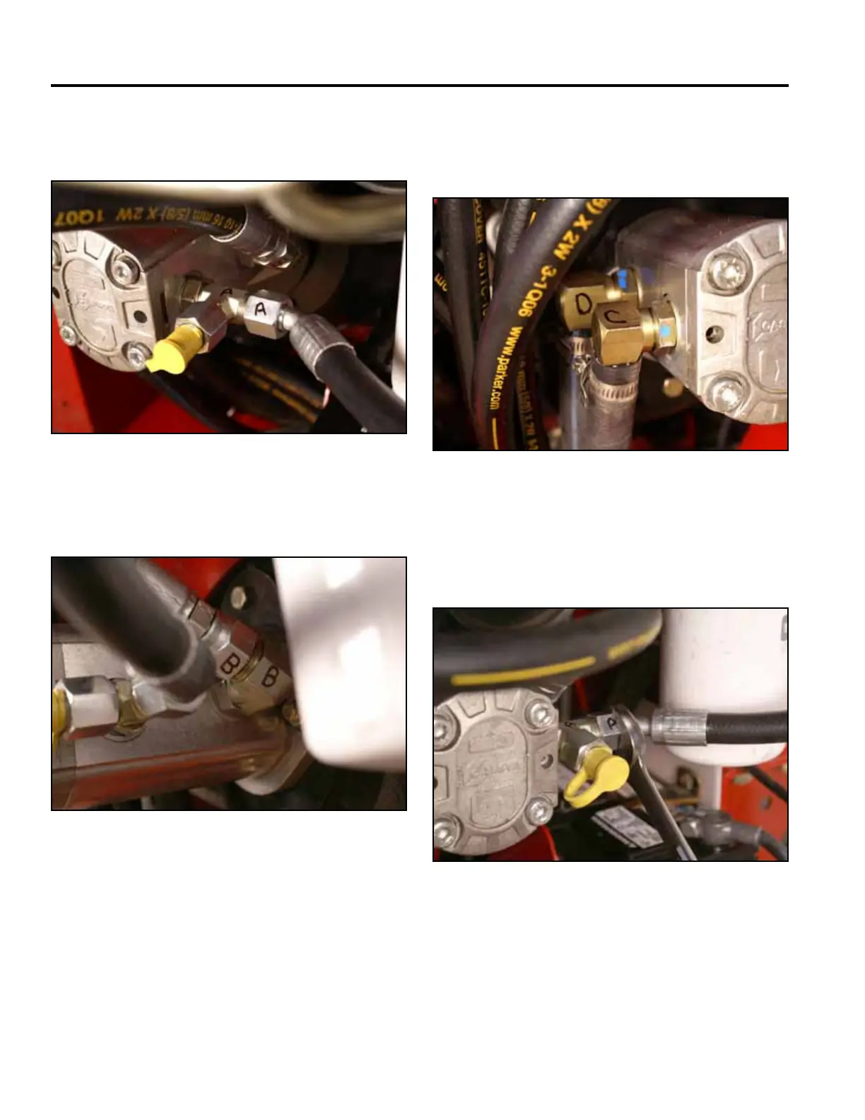
9. Mark the tandem pump lines and ttings as follows:
A. Pump pressure line to loader valve (Fig. 0949)
C. Suction line from the tank (smaller tting)
D. Suction line from the tank (larger tting) (Fig. 0951)
Fig 0949 PICT-4765
Fig 0951 PICT-4767
10. Using a 15/16” wrench, remove the pump pressure
line marked with an A from the hydraulic tandem
pump (Fig. 0952).
B. Pump pressure line to auxiliary valve (Fig. 0950)
Fig 0952 PICT-4768a
Fig 0950 PICT-4766a