HYDRAULIC SYSTEM
6-40 Rev. 000 TX525 Service Manual
c. Using a 1-1/8” wrench, install the pump pressure
line (marked B) to the pump tting marked B
(Fig. 0981).
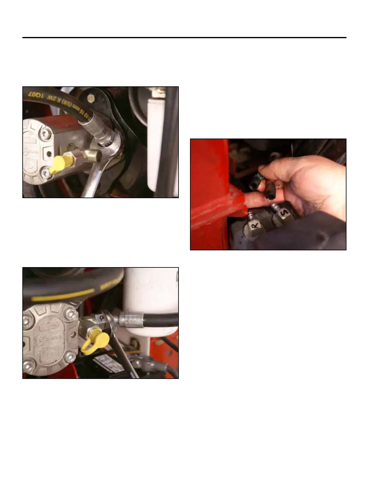
10. Slide the 2 fuel lines onto the fuel tank ttings. Note
the location markings (Fig. 0983).
S - Fuel suction line
R - Fuel return line
Note: Before installing the fuel tank in the unit,
disengage the park brake and start the unit.
Refer to “Purging Air Procedure” on page
9-19. Check for any leaks at the hydraulic
ttingsandhoses.
Fig 0981 PICT-4770a
Fig 0983 PICT-4265
d. Using a 15/16” wrench, install the pump pres-
sure line (marked A) to the pump tting marked
A (Fig. 0982).
Fig 0982 PICT-4768a