HYDRAULIC SYSTEM
6-41TX525 Service Manual Rev. 000
11. Position the 2 fuel hose clamps and tighten to se-
cure the fuel lines to the fuel tank ttings (Fig. 0984).
13. Position the rear frame cover to the rear of the
frame. Using 3/4” and 1/2” sockets, install 7 bolts
and nuts to secure the rear frame cover to the frame
and fuel tank bracket (Fig. 0986).
Note: The rear of the machine may have to be lifted
to reposition the jack stands so that the rear
frame cover can be installed.
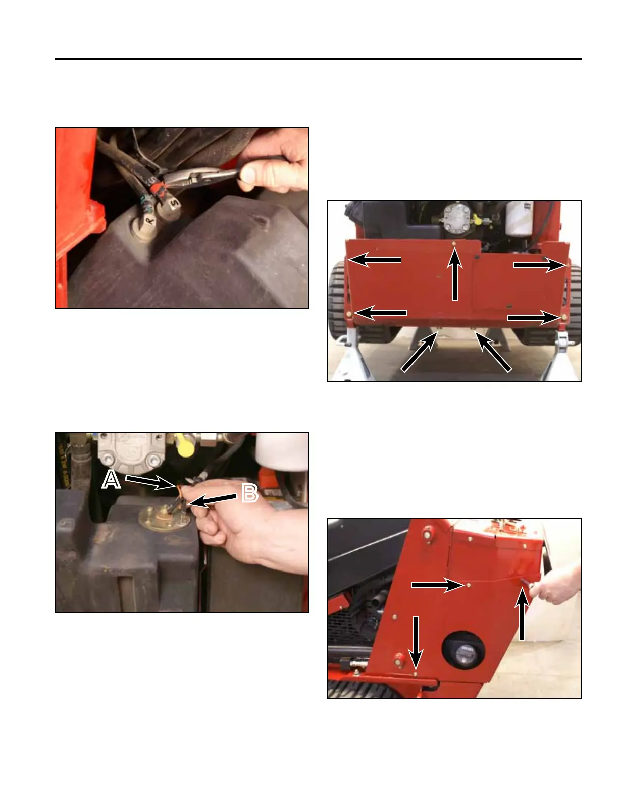
A. Center terminal (orange wire)
B. Outside terminal (black wire)
Fig 0984 PICT-4264
Fig 0986 PICT-4259
14. Position the left hand rear cover support panel to
the tower. Using a 3/8” socket, install 3 screws to
secure the left rear cover support panel to the tower
assembly. Repeat to install the right hand rear cover
support panel (Fig. 0987).
12. Position the fuel tank into the rear of the frame.
Connect the two wires (black and orange) to the fuel
sending unit located on the top of the fuel tank (Fig.
0985).
Fig 0987 PICT-4256
Fig 0985 PICT-4262a
A
B